Instrukcja obsługi Festo DADP-SP-G9-6-F
Festo Nie skategoryzowane DADP-SP-G9-6-F
Przeczytaj poniżej 📖 instrukcję obsługi w języku polskim dla Festo DADP-SP-G9-6-F (2 stron) w kategorii Nie skategoryzowane. Ta instrukcja była pomocna dla 18 osób i została oceniona przez 2 użytkowników na średnio 4.4 gwiazdek
Strona 1/2
DADP-SP-G9-...-F
Stop kit
Festo SE & Co. KG
Ruiter Straße 82
73734 Esslingen
Germany
+49 711 347-0
www.festo.com
Assembly instructions
8195146
2023-07a
[8195148]
8195146
Translation of the original instructions
© 2023 all rights reserved to Festo SE & Co. KG
1
Applicable documents
All available documents for the product
è
www.festo.com/sp.
DocumentProductContents
Operating instructionMini slide DGSS–
Operating instructionShock absorber DYEF, DYSS–
Tab. 1:
Applicable documents
2Safety
2.1
Safety instructions
–Only mount the product on components that are in a condition to be safely
operated.
2.2Intended use
The stop kit in combination with a shock absorber on the mini slide DGSS cush-
ions its extended end position.
3Additional information
–
Contact the regional Festo contact if you have technical problems
è
www.festo.com.
–
Accessories
è
www.festo.com/catalogue.
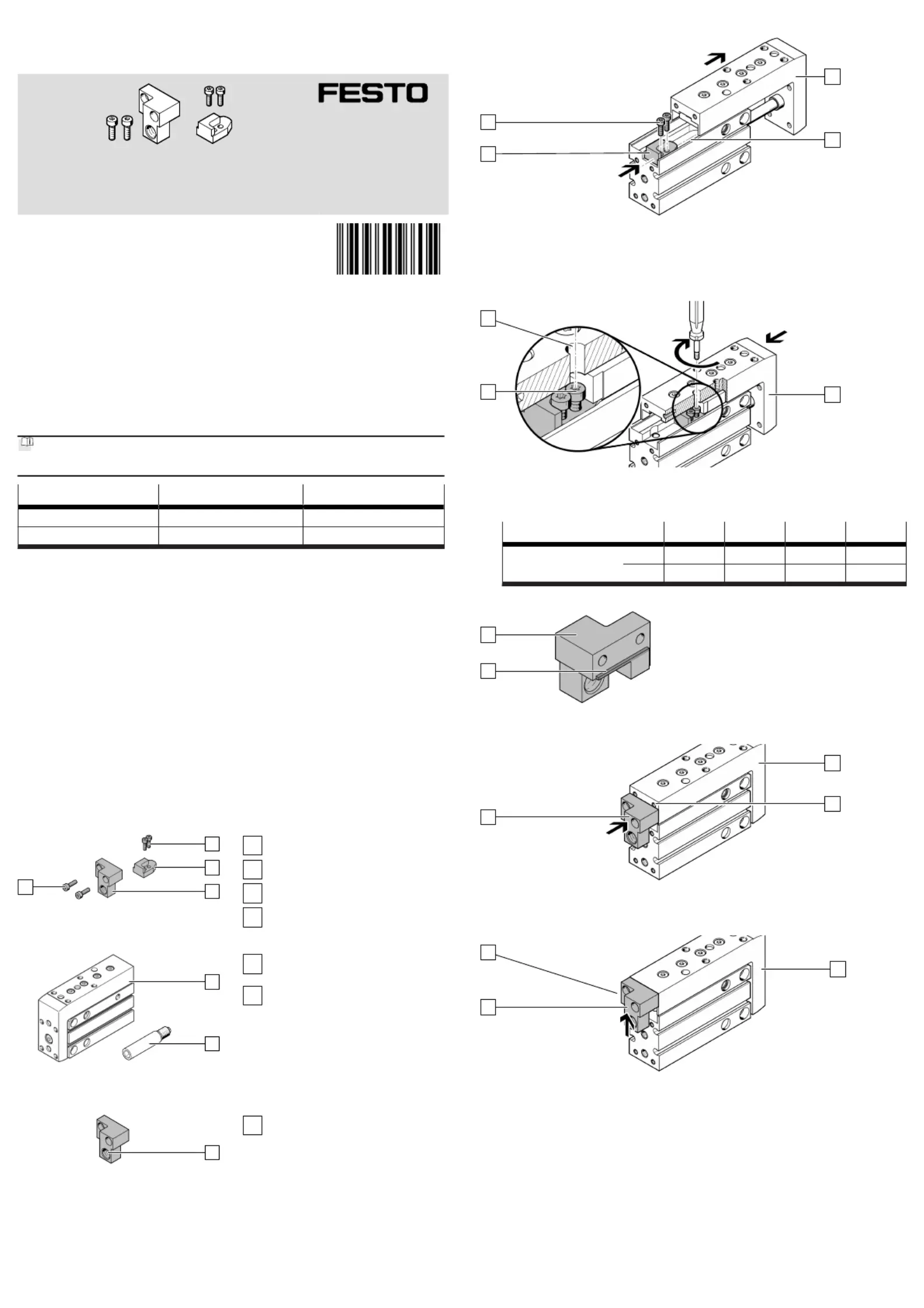
4Product Range Overview
4.1
Scope of delivery
1
2
3
4
Fig.1
1
Screw (2x)
2
Stop (1x)
3
Stop element (1x)
4
Screw (2x)
4.2
Not in scope of delivery
5
6
Fig.2
5
Mini slide (1x)
DGSS
6
Shock absorber (1x)
DYEF-G8/DYSS-G8
5
Product design
Z
Fig. 3:
Product design
Z
Thread for shock absorber
6Assembly
1
A
B
2
Fig. 4:Pushing in stop
1.Extend the slide[A] manually.
2.Slide the stop into the slot[B].2
3.Insert the screws into the holes of the stop.12
4.Slide the stop to the end of the slot[B].2
A
C
1
Fig. 5:Mounting stop
1.
Position the slide[A] so hole[C] is aligned with a screw.1
2.
Tighten the screw. Observe the tightening torque.1
DADP-SP-G9-6-10-16-20
ScrewM2 x 6M2.5 x 8M2.5 x 8M3 x 12
[Nm]0.3 ±15%0.5 ±15%0.7 ±15%0.9 ±15%
3.
Repeat this process for the second screw.1
C
3
Fig. 6:
Note the stop bar
•
When installing the stop element, note the position of the stop bar[C].3
3
D
A
Fig. 7:
Aligning stop element
1.
Retract the slide[A] manually.
2.Position the upper edge of the stop element at the level of the thread[D].3
3
A
C
Fig. 8:
Attaching stop bar
1.Push the stop element upwards to the stop.3
Ä
The stop bar[C] is in contact with the slide[A].
2.Hold this position.
Specyfikacje produktu
| Marka: | Festo |
| Kategoria: | Nie skategoryzowane |
| Model: | DADP-SP-G9-6-F |
Potrzebujesz pomocy?
Jeśli potrzebujesz pomocy z Festo DADP-SP-G9-6-F, zadaj pytanie poniżej, a inni użytkownicy Ci odpowiedzą
Instrukcje Nie skategoryzowane Festo

30 Marca 2025
30 Marca 2025
30 Marca 2025
30 Marca 2025
30 Marca 2025
30 Marca 2025
30 Marca 2025
30 Marca 2025
30 Marca 2025
30 Marca 2025
Instrukcje Nie skategoryzowane
Najnowsze instrukcje dla Nie skategoryzowane
9 Kwietnia 2025
9 Kwietnia 2025
9 Kwietnia 2025
9 Kwietnia 2025
9 Kwietnia 2025
9 Kwietnia 2025
9 Kwietnia 2025
9 Kwietnia 2025
9 Kwietnia 2025
9 Kwietnia 2025