Instrukcja obsługi PCE Instruments PCE-VT 204
PCE Instruments Sprzęt pomiarowy PCE-VT 204
Przeczytaj poniżej 📖 instrukcję obsługi w języku polskim dla PCE Instruments PCE-VT 204 (30 stron) w kategorii Sprzęt pomiarowy. Ta instrukcja była pomocna dla 20 osób i została oceniona przez 6 użytkowników na średnio 4.6 gwiazdek
Strona 1/30
Manual
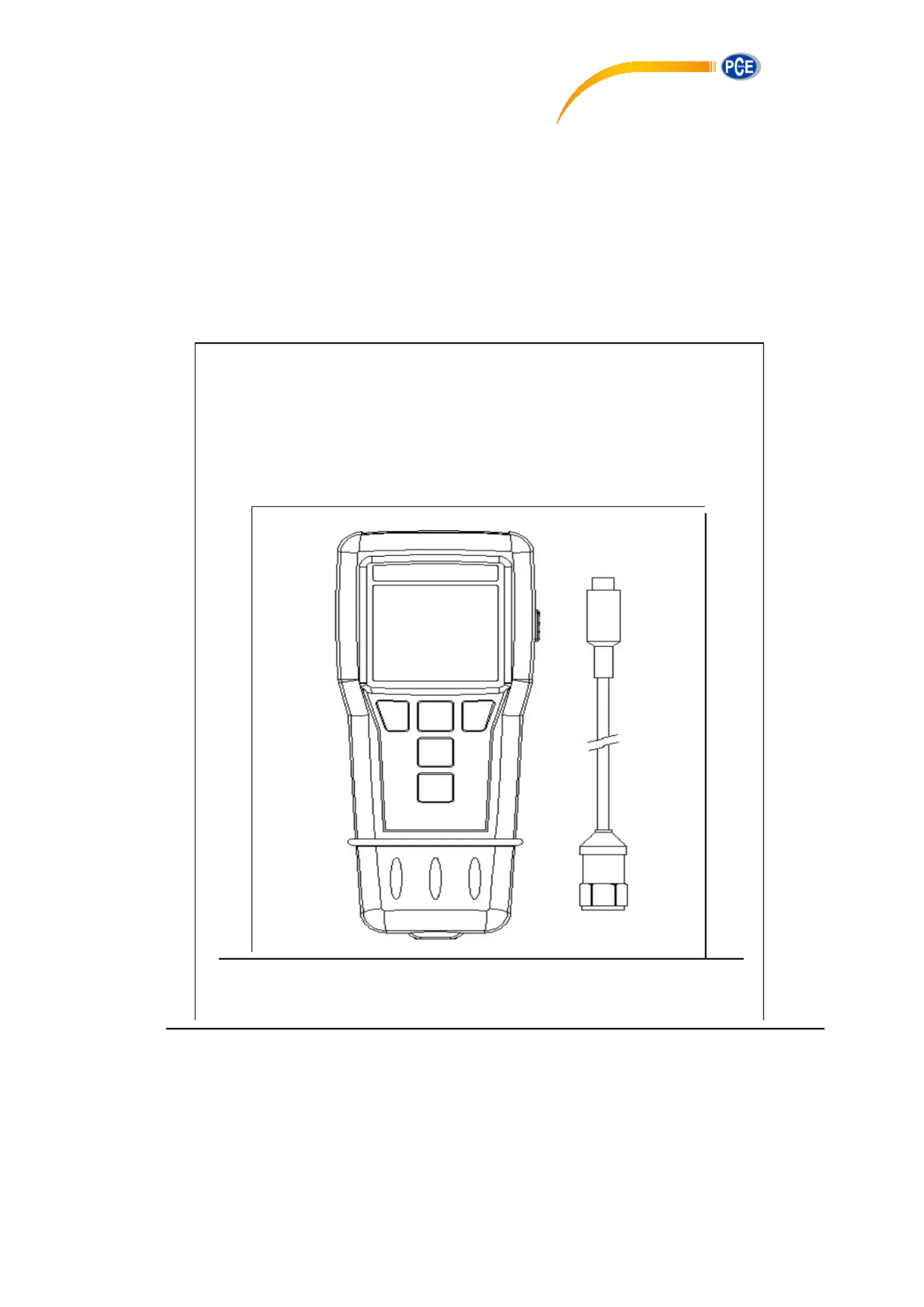
Vibration Analyser
PCE-VT 204
PCE Americas Inc.
711 Commerce Way
Suite 8
Jupiter
FL-33458
USA
From outside US: +1
Tel: (561) 320-9162
Fax: (561) 320-9176
info@pce-americas.com
www.pce-instruments.com/english
www.pce-instruments.com
PCE Instruments UK Ltd.
Units 12/13
Southpoint Business Park
Ensign way
Hampshire / Southampton
United Kingdom, SO31 4RF
From outside UK: +44
Tel: (0) 2380 98703 0
Fax: (0) 2380 98703 9
info@pce-instruments.com
Specyfikacje produktu
| Marka: | PCE Instruments |
| Kategoria: | Sprzęt pomiarowy |
| Model: | PCE-VT 204 |
Potrzebujesz pomocy?
Jeśli potrzebujesz pomocy z PCE Instruments PCE-VT 204, zadaj pytanie poniżej, a inni użytkownicy Ci odpowiedzą
Instrukcje Sprzęt pomiarowy PCE Instruments

29 Marca 2025
28 Marca 2025
28 Marca 2025
28 Marca 2025
28 Marca 2025
28 Marca 2025
28 Marca 2025
28 Marca 2025
28 Marca 2025
28 Marca 2025
Instrukcje Sprzęt pomiarowy
Najnowsze instrukcje dla Sprzęt pomiarowy
3 Kwietnia 2025
3 Kwietnia 2025
3 Kwietnia 2025
3 Kwietnia 2025
3 Kwietnia 2025
3 Kwietnia 2025
3 Kwietnia 2025
3 Kwietnia 2025
3 Kwietnia 2025
3 Kwietnia 2025