Instrukcja obsługi Sanwa CD800a
Przeczytaj poniżej 📖 instrukcję obsługi w języku polskim dla Sanwa CD800a (2 stron) w kategorii multimetr. Ta instrukcja była pomocna dla 52 osób i została oceniona przez 3 użytkowników na średnio 4.9 gwiazdek
Strona 1/2
CD800a
DIGITAL MULTIMETER
INSTRUCTION MANUAL
--1
【】1SAFETY PRECAUTIONS B
efo, ree usrtheow ead flloingsafetrectns.y pauio
This instruction manual explains how to use your new digital multimeter
CD008a fely. fore us ea ad ts l osaBee,plserehimanuathorughly. A gfterreadin
itke, ep it toer wh gethitthoder puct for efrerence to int whe necessary.
TheinstructiongivenundertheheadingofWARNING”must “ be
fto evollod weprent acdtcienal burn orl eectrical s.hock
1-1Explanation of Warning Symbols
Themeaningofthesymbolsusedinthismanualandattachedtoth e
product is as follows.
Very important instruction for safe use.
Thewarningmessagesareintendedtopreventaccidents to
operating personnel such as burn and electrical shock.
Thecautionmessagesareintendedtopreventdamagetoth e
instrument.
:::GroundDiode Fuse
:::BuzzerCapacitanceΩResistance
::Direct current(DC)HzFrequency
%
::Duty cycle~Alternating current(AC)
:ⅡDouble insulation(Protection Class)
+-:Plus input (Red):Minus input(Black)
1-2Warning Instruction for Safe Use
Toensurethemeterisusedsafely,besuretoobservetheinstructio n
when using the instrument.
1.Never use meter on the electric circuits that Exceed 3 kVA.
2.Never apply an input signal exceeding the maximum rating input value.
3.Never use meter if the meter or test leads are damaged or broken.
4. 4PayspecialattentionwhenmeasuringthevoltageofAC30Vrms(42.
V peak) or DC 60 V or more to avoid injury.
5. tNeverusemeterformeasuringthelineconnectedwithequipmen
(i.e.motors)thatgeneratesinducedorsurgevoltagesinceitma y
exceed the maximum allowable voltage.
6.Never use uncased meter.
7. a aBesuretousefuseofthespecifiedratingortype.Neveruse
substitute of the fuse or never make a short circuit of the fuse.
8. gWhenconnectinganddisconnectingthetestleads,firstconnectin
thegroundlead(blackone).Whendisconnectingthem,thegroun d
lead must be disconnected last.
9. nAlwayskeepyourfingersbehindthefingerguardsontheprobewhe
making measurements.
WARNING
【】2APPLICATION AND FEATURES
2-1Applications
This instrument is portable digital multimeter designed for measurement
of weak current circuits. It plays an important role in circuitry analysis by
usingadditionalfunctionsaswellasmeasurementsofsmalltyp e
communication equipment, electrical home appliance, lighting voltage and
batteries of various type.
10.Be sure to disconnect the test pins from the circuit when changing
the function.
11. dBeforestartingmeasurement,makesurethatthefunctionan
range are properly set in accordance with the measurement.
12.Never use meter with wet hands or in a damp environment.
13. .Neveropentestercaseexceptwhenreplacingbatteriesorfuse
Do not attempt any alteration of original specifications.
14. cDonotusethedevicenearanitemofstrongelectromagneti
generation or a charged item.
15. eToensuresafetyandmaintainaccuracy,calibrateandcheckth
tester at least once a year.
16.The multimeter is for indoor use only.
Function
V
DCAC 600 V・
DC 600 V
AC 600 V or Peak
Max 840 V
Ω///
Voltage and
Current input
prohibited
Hz / %
DCAC 600 V・
mA
DCAC 400 mA・
0.5 A / 250 V Fuse
Input
terminals
Maximum rating
input value
Maximum overload
protection input
1-3Overload protections
(Red)
(Black)
+
-
--2
※AC voltage is regulated by rms, valus of sinusoidal wave.
--7
1) Applications
The quality of diodes is tested.
2) How to use
①ΩSet the FUNTION switch at ///.
②Selectby pressing the SELECT button.
③
Apply the black test pins to the cathode of the diode and the red test pin to the anode.
④Make sure that the display shows a diode forward voltage drop.
⑤
Replace the red and black test pins, make sure that the display is “OL” reading.
⑥
After measurement, release the red and black test pins from the object measured.
●The input terminals open voltage is about 1.5 V
3) Measurement procedure
①ΩΩSet theFUNTIONswitchat/// andselectwith eth
SELECT button.
②Apply the red and black test pins to an object to measure.
③The reading is shown in the display.
④
After measurement, release the red and black test pins from the object measured.
Note : eIfmeasurementislikelytobeinfluencedbynoise,shieldth
objecttomeasurewithnegativepotential(COM).Iffinge a r
touchestestpinduringmeasurement,measurementwill a be
influenced by the resistance in the human body, and that results
in measurement error. Open Circuit Voltage: <0.4 VDC typical.
●Whehn te presence of volgeesta, ristncaeasureman t work. meent cno
Ω
Resistor
③
④④
②
①
5-4Testing Diode ()
Never apply voltage to the input terminals.
WARNING
Diode
④
⑥⑥
③
⑤
AnodeCathode
①
②
--6
3) Measurement procedure
①Set etheFUNCTIONswitchat“V”andselecteitherDCorACwithth
SELECT button.
②Apply the red and black test pins to the circuit to measure.
●For emeasurementofDCV,applytheblacktestpintothenegativ
potential side of the circuit to measure and the red test pin to the
positive potential side.
●For measurement of ACV, apply the red and black test pins to the
circuit to measure.
③The reading of Voltage is shown on the display.
④After emeasurement,releasetheredandblacktestpinsfromth
object measured.
◇Readings are unstable when test leads are opened.
◇Accuracy ~isguaranteedinthecaseofsinewave(Bandwidth40
400 Hz)
◇400 mV AC range is not specified.
◇In the manl muaode of the V function, t a can be set to theACheCD800
400 range and sho ate lue. t i ca notmVwsanppimaroxvaButsacurcyis
guarante.ed
◇~In the AC 4 V range, a figure of about 39 counts will stay on even if
no input signal is present. But it is not malfunction.
◆Use Hz/% function for making Hz and duty cycle measurements.
V
Battery
Outlet
DCV measurement
ACV measurement
③
④④
④④
①
②
1) Applications
Resistance of resistors and circuits are measured.
2) Measuring ranges
6 ranges from 400to 40 M.ΩΩ
5-3Resistance Measurement ()Ω
Never apply voltage to the input terminals.
WARNING
【】5MEASUREMENT PROCEDURE
5-1Start-Up Inspection
1. Make sure that no low battery indication appear in the display.
2. Never use meter if the meter or test leads are damaged or broken.
3. Check continuity of test leads & fuse.
WARNING
※No display may suggest that a battery be exhausted.
START
No damaged
Damaged
Main unit
and test leads
damaged?
The buzzer sounds?
Yes
No
②Short the red and
black test pins.
Stop using it and have
it repaired.
①
Set the function at
"
"
.
Check continuty of test
leads.
No problem.
Start measurement.
①
Check
②
5-2Voltage measurement
1. Ner plveapy an puint sigaln eeehxcding te maximum ratiut.ng inp value
2.
Be s toure dioscnnect ttheest pinomths fr e ciuirct henw changing the funion.ct
3. Always ke ur fieepyongrsbe hid nthngei fer grds ohe probe enuan twh
mang remes.kimeasunt
WARNING
--5
DCV / ACVMaximum rating input value 600 V DC/AC:
1) Applications
DCV : Voltage of the battery and DC circuit are measured.
ACV : Sine wave AC voltage, such as lighting voltage, is measured.
2) Measuring ranges
DCV : 5 ranges from 400 mV to 600 V
ACV : 4 ranges from 4 V to 600 V
--4
In the case of action or cancel that function as follows, do not turn the
function switch in the condition applied input.
WARNING
【】4DESCRIPTION OF FUNCTIONS
4-1Function Switch
Turnthisswitch,toturnonandoffthepowerandtoselectth e
functions of V, , Hz/%, mA~Ω///~
4-2SELECTMeasurement Function Select:
When theSELCT Ebutnto is pressed (→), the nofuctins chae as fws.ngollo
・:→In the case of V, mA, the modes change as→~
・
In the case of Ω,,, e, the modes chang:Ω→→→→Ω
4-3RANGERange Hold:
PresstheRANGEbuttonmomentarytosetthemanualrangemode ,
then ‘AUTO’ disappears in the display. In manual range mode, press the
button again to step through the ranges. To return to the auto mode,
press the button for 1 sec. or more, then ‘AUTO’ is shown.
※Manual , emodeisnotavailableinHz,dutymeasurement,diod
check, cont. buzzer functions.
4-4RELRelative Mode△:
Relativezeroallowstheusertooffsetthemeterconsecutiv e
measurementitthiss wh e dplaingeay rdinferncealg as the ree vue. Prses
the △REL bomentutton marily to activate d to anexit rro mode.elative ze
4-5HOLDData Hold:
When the HOLD button is pressed, the display is hold (‘DH’ is shown
onthedisplay).Thedisplaywillnotbechangedwhilethefunction is
active. s e tt Presthbuon
again
to ca the funcn‘’ on enceltio.(DHth
display disappears.)
※DATA HOLD function does not work when measuring frequency.
4-6Hz/%Frequency and duty cycle select button:
Frequencyanddutycyclemeasurementfunctionsareactivatedalternativel y
by pressing the button. In the case of the mode change as Hz →%
4-7Auto Power Off
The w er a wer nn smeterillntelowpocosumptioleep mode autcomatially
toten exd battery fe ter appxy 30 u no func sliafroimatelmintesoftionwitch
orpushutt bon opas. To w up e t to Power Off,ertionakethmeerfromAu
pressanybuttonsmomentarilyorturnthefunctionswitchtotheOF F
po Then tu basition.rnck agaonindiablehetoowre. To s t Au Perfffea O tu,
prsse Ethe SLECT bun wttohile turinng the fuonctin switch on.
※Always turn the function switch to the OFF position when the meter
is not in use.
--8
②
5-5Checking Continuity ()
Never apply voltage to the input terminals.
WARNING
1) Applications
Checking the continuity of wiring and selecting wires.
2) How to use
①ΩSet the FUNTION switch at ///.
②Selectby pressing the SELECT button.
③Apply the red a nd blacktepist ns to a c ndu mse.ircuitor coctotor eaur
④The continuity can be judged by whether the buzzer sounds or not.
⑤
After measurement, release the red and black test pins from the object measured.
●ΩThreshold : 10~120
⑤⑤
④
Extension cord
①
③
5-6Capacitance Measurement ()
Never apply voltage to the input terminals.
WARNING
1) Applications
Measurescapacitanceoflowleakagecondensersuchasfil m
condenser.
2) Measuring ranges
5 ranges from 50.00 nF to 100.0F (Auto range).μ
1. Discharge the capacitance before measurement.
2. This is not suitable for measurement of electrolytic condenser such
as a large leakage condenser.
3. It takes a while to measure large capacitance.
CAUTION
--9
3) Measurement procedure
①ΩSet the FUNTION switch at ///.
②Selectby pressing the SELECT button.
③Press the REL button for zero setting (00.00 nF).
④Apply the red and black test pins to a conductor to measure.
⑤Read the value on the display.
⑥
After measurement, release the red and black test pins from the object measured.
●Manual range is not available in capacitance measurement.
●
Readings are unstable because of stray capacitance in test leads or noise.
5-7Hz / % Measurements ( Hz / % )
Never apply an input signal exceeding the maximum rating input value.
WARNING
Capacitor
①
②
⑤
⑥⑥
④
③
1) Applications
Measures frequency and duty of any circuit.
2) Measuring ranges
6 ranges from 5 Hz to 100 kHz (Auto range)
Duty Cycle : 20 %~80 %
3) Measurement procedure
①Set the function switch at Hz / % function.
②Select Hz by pressing Hz/% selection button.
③Apply the red and black test pins to a conductor to measure.
④Read the value on the display.
⑤
After measurement, release the red and black test pins from the object measured.
●HOLD function does not work in Frequency measurement function.
Hz
%
①
④
⑤⑤
③
②
--10
5-8Current Measurement
1. Never apply voltage to the input terminals.
2. Be sure to make a series connection via load.
3. Do not apply an input exceeding the maximum rated current to the
input terminals.
4. eBeforestartingmeasurement,turnOFFthepowerswitchofth
circitpaatethmeasriartanenconetesu to ser e ung p, d th nct the t
leads firmly.
WARNING
mAmA
Power source
Load
Power source
Load
(×)
(○)
●:DCmAMaximum rating input value 400 mADC
●:ACmAMaximum rating input value 400 mAAC
1) Applications
DCACurrent in batteries and DC circuits is measured.:
ACACurrent in AC circuits is measured.:
2) Measuring ranges
DC/ACmA2 ranges for 400.0 mA and 40.00 mA.:
3) Measurement procedure
①
Set the function switch at “mA” and select either DC or AC with the SELECT button.
②
In the circuit to measure and apply the red and black test pins in series with load.
●For measurement of DCA, apply the black test pin to the negative
potential side of the circuit to measure and the red test pin to the
positive potential side in series with load.
●For measurement of ACV, apply the red and black test pins to the
circuit to measure in series with load.
③Read the value on the display.
④
After measurement, remove the red and black test pins from the circuit measured.
◆Use Hz/% function for making Hz and duty cycle measurements.
mA
Power
source
①
③
④④
②
Load
--11
【】6MAINTENANCE
1. The section is very important for safety. Read and understand the
following instruction fully and maintain your instrument properly.
2. aTheinstrumentmustbecalibratedandinspectedatleastonce
year to maintain the safety and accuracy.
WARNING
6-1 Maintenance and inspection
1) Appearance
●Is the appearance not damaged by falling?
2) Test leads
●Is the cord of the test leads not damaged?
●Is the core wire not exposed at any place of the test leads?
Note:
If the built-in fuse is blown, only the current measurement becomes impossible.
Note:
Make sure that the test leads are not cut, referring to the section 5-1.
6-2Calibration
Themanufacturermayconductthecalibrationandinspection.Fo r
more information, please contact the dealers.
6-3Battery and Fuse Replacement
1. If the rear case or the battery lid is removed with input applied to
theinputterminals,youmaygetelectricalshock.Beforestartin g
the work, always make sure that no input is applied.
2. Before starting the work, be sure to turn OFF the main unit power
and release the test leads from the circuit.
3. Be sure to use a fuse of the specified rating or type. Never use a
substitute of the fuse or never make a short circuit of the fuse.
WARNING
Set battery with its polarities facing in the correct directions.
CAUTION
Rear case
Battery lid
Battery lid screw
R6(UM-3)
①Remove the battery lid screw with a screwdriver.
②Take out the battery or fuse and replace it with a new one.
③Attach the battery lid and fix with the screw.
Fuse
0.5 250 A/V
F1176
φ5×20 mm
Blowout capacity
: 1.5 kA
20~80 %
±(0.5 %rdg+5dgt)
直流電流
DCmA
±(2.2 %rdg+5dgt)
DC Current
±(2.8 %rdg+5dgt)
※オートレンジのみ。
※Auto range only.
5 Hz~60 Hz 3 Vrms~30 Vrms
60
Hz~200 Hz 4.9 Vrms~30 Vrms
デューティー比
%
Duty Cycle
周波数
Hz
Frequency
5.000 Hz
50.00 Hz
500.0 Hz
±(0.5 %rdg+3dgt)
5.000 kHz
50.00 kHz
100.0 kHz
--15
※トランスや大電流路など強磁界の発生している近く、また無線機など強電界の
発生している近くでは正常な測定ができない場合があります。
確度計算方法/ Accuracy calculation
例)直流電圧測定(DCmV) / For example…Measurement 400 mVDC Range.
表示値/ Display value : 100.0[mV]
レンジ確度/ Accuracy : 400.0[mV] レンジ/ Range…±(0.3 %rdg+4dgt)
誤差/ Error : ±(100.0[mV]×0.3 %rdg+4dgt)=±0.7[mV]
計算式/ Calculation : 100.0[mV]±(100.0[mV]×0.3 %rdg+4dgt)
真値/ True value : ln a range of 099.3[mV]~100.7[mV]の範囲内。
※400.0[mV]レンジにおける4[dgt]とは、0.4[mV]に相当します。
※4[dgt] in the 400.0[mV]range correspond to 0.4[mV]
ここに掲載した製品の仕様や外観は改良等の理由により、予告なしに変更す
ることが有りますのでご承知ください。
Specifications and external appearance of the product described above may
be revised for modification without prior notice.
400.0 mA
40.00 mA
400.0 mA
40.00 mA
約1Ω
Approx. 1Ω
ヒューズ抵抗を除く
Without resistance
of Fase
約1Ω
Approx. 1Ω
ヒューズ抵抗を除く
Without resistance
of Fase
Checking Continuity
10~120Ω以下で発音・開放電圧:DC約0.4 V
Buzzer sounds at less than 10~120Ω・Open voltage:Approx.DC 0.4 V
開放電圧:DC約1.5 V
Open voltage: Approx. DC 1.5 V
Testing Diode
交流電流
ACmA
AC Current
※正弦波交流おける確度
確度保証周波数範囲40~400 Hz
※Accuracy in the cace of sin
wave 40~400 Hz
※オートレンジのみ。
※Auto range only.
1 Hz~1
k
Hz 4 Vrms~250 Vrms
1
k
Hz
~100 kHz 4 Vrms~
20 Vrms
--14
400.0 mV
±(0.7 %rdg+3dgt)
≧100 MΩ
ΩM 11 .xorppAV 000.4圧電流直
DCV40.00 V
±(1.1 %rdg
+
3dgt)
DC Voltage400.0 V
600 V
4.000 V
±(1.6 %rdg+9dgt)
Approx. 11 MΩ
40.00 V
400.0 V
±(1.6 %rdg+5dgt)
600 V
400.0 Ω
±(1.5 %rdg+5dgt)
4.000 kΩ
抵抗40.00 kΩ
±(1.2 %rdg+5dgt)
Ω400.0 kΩ
Resistance
4.000 MΩ
±(2.0 %rdg+3dgt)
50.00 nF
静電容量500.0 nF
5.000μF
±(5.0 %rdg+10dgt)
Capacitance50.00μF
100.0μF.
8-2測定範囲及び確度/ Measurement Range and Accuracy
確度保証範囲:温度23±5 ℃ 湿度:80 %R.H.以下 結露のないこと
Accuracy assurance range : 23±5 ℃&less than 80 % R.H. No Condensation
rdg(reading):読取値、dgt(digit):最終桁のカウント数
ファンクション&レンジ
Function&Range
確 度
Accuracy
入力抵抗
Input Impedance
備 考
Remarks
40.00 MΩ
±(4.0 %rdg+3dgt)
約10 MΩ
Approx. 10 MΩ
約10 MΩ
Approx. 10 MΩ
交流電圧
ACV
AC Voltage
開放電圧:DC約0.4 V
Open voltage : Approx.DC 0.4 V
測定電流は被測定抵抗の抵抗によって変化します。
The measurering current changes according to the
resistance of the resistor to measure.
※オートレンジのみ。
※Auto range only.
表示されている値をリラティ機能によっブて
キャンセルした後の確度。
Accuracywasmeasuredaftercancelingdidla py
value by relative key
※正弦波交流おける確度
確度保証周波数範囲40~400 Hz
※ eAccuracyinthecaceofsinwav
40~400 Hz
MeasurinmethodgΔΣ
Displays3 3/4 digit, 4000 count
Sampling RatApprox.3 times/seec
Over ranging lndication
“OL” mark indication (except AC/DC 600 V ranges)
Low Battery IndicatioBelow approx. 2.4 V ” mark indication“n
Environmental ConditioOperating altitude <2000 m / Pollution degrene
Ⅱ
Power SupplyR06×2
AC sensorinAverage sensoringg
Battery Lif30 min. (auto power savee)
DimensionL 176 mm×W 104 mm×H 46 mm
MassgApprox. 340
Power consumptioApprox. 7 mW TYP. (at DCVn)
Battery lifApprox. 500 hours at DCeV
Fuse
0.5 A / 250 V Fast Acting Fuse, Parts number:F1176
AccessorieslInstruction manua
2) Rr ngepaiduri the rrawanty pd:erio
The d meter wfaileill be pairereacd incordance with the conditionsp stiulated in
7-1 Warrantd Pis.y anrovion
3)Rr terepaiaf the warranty period has expired:
In some cases,repair andtransportation costmay becomehigher thanthe price of
the product. Please contact Sanwa authorized agent / service provider in advance.
Theminimumretentionperiodofservicefunctionalpartsisyearsafterth 6 e
discontinuationofmanufacture.Thisretentionperiodistherepairwarrant y
period.Pleasenote,however,ifsuchfunctionalpartsbecomeunavailablefo r
reasonsofdiscontinuationofmanufacture,etc.,theretentionperiodma y
become shorter accordingly.
4)ecauPrtions when sending the ropduct to breede pair
To ensure the safety of the product during transportation, place the product
in a bo
x
thatislargerthantheproduct 5 stimesormoreinvolumeandfillcushionmaterial
fullyand thenclearlymark“Repair ProductEnclosed”on theboxsurface. Thecos t
of sending and returning the product shall be borne by the customer.
7-3eSANWA Websit
http://www.sanwa-meter.co.jp
E-mail: exp_sales@sanwa-meter.co.jp
--13
【】8SPECIFICATIONS
8-1General Specification
Storage temperature /
humidity range
-105070%R.H.max.Nocondensation.(remov ℃~℃ e
batteries)
Automaticselection(isindicatedwhennegativ “” - e
voltage is inputted.)
Range Selection
Polarity Indication
Operating temperature
5 % r℃~40℃humidityrange:Maximum80RHfo
temperaturesupto31decreasinglinearlyto50 ℃ % RH
at 40 ℃
Auto and Manual ranges
(Manual range or Auto renge only)
6-4Storage
1. The panel and the case are not resistant to volatile solvent and must
not be cleaned with thinner or alcohol.
2. For cleaning, use dry, soft cloth and wipe it lightly.
3. The panel and the case are not resistant to heat. Do not place the
instrument near heat-generating devices (such as a soldering iron).
4. Do not store the instrument, in a place where it may be subjected
to vibration or from where it may fall.
5. For storing the instrument, avoid hot, cold or humid places or places
under direct sunlight or where condensation is anticipated.
CAUTION
--12
【】7AFTER-SALE SERVICE
7-1Warranty and Provision
Sanwaofferscomprehensivewarrantyservicestoitsend-usersandtoit s
productresellers.UnderSanwa'sgeneralwarrantypolicy,eachinstrumen t
iswarrantedtobefreefromdefectsinworkmanshipormaterialunde r
normal use for the period of one (1) year from the date of purchase.
Thiswarrantypolicy isvalidwithinthecountry ofpurchaseonly,and applied
only to the product purchased from Sanwa authorized agent or distributor.
Sanwareservestherighttoinspectallwarrantyclaimstodetermineth e
extenttowhichthewarrantypolicyshallapply.Thiswarrantyshallnotappl y
to fuses, s battdipoblessaeries, or a pru s, wch h bnnyodctorparthiaveee
subject to one of the following causes:
1.failureduetoimproperhandlingorusethatdeviatesfromth A e
instruction manual.
2.failureduetoinadequaterepairormodificationbypeopleothertha A n
Sanwa service personnel.
3.failureduetocausesnotattributabletothisproductsuchasfire A ,
flood and other natural disaster.
4. Non-operation due to a discharged battery.
5. A failureordamageduetotransportation,relocationordroppingafterth e
purchase.
7-Repai2r
Customers are asked to provide the following information when requesting services:
1. Customer name, address, and contact information
2. Description of problem
3. Description of product configuration
4. Model Number
5. Product Serial Number
6. Proof of Date-of-Purchase
7. Where you purchased the product
Pe co n tr e / dleasntactSawaauhoizedagntisritbutoseceder / rvi provir,
listedinourwebsite,
tinyourcountrywithaboveinformation.Aninstrumen
sentto Sanwa / / agentdistributorwithoutthoseinformation willbereturne d
to the customer.
Note:
1) Prior to requesting repair, please check the following:
Cy of b-in tty, li ins dapacittheuiltbaerpoartyoftallationan
discontinuity of the test leads.
CaD800
4000 Count
SELECT
RANGE RELHOLDHz
△
%
AUTOPO F WER OF
DIGITAL
MULTIMETER
OFF
V
Hz
mA
MAX 400mA
FUSED
600V MAX(CAT.)
%
~
~
~
Ⅲ
Ω
+ -
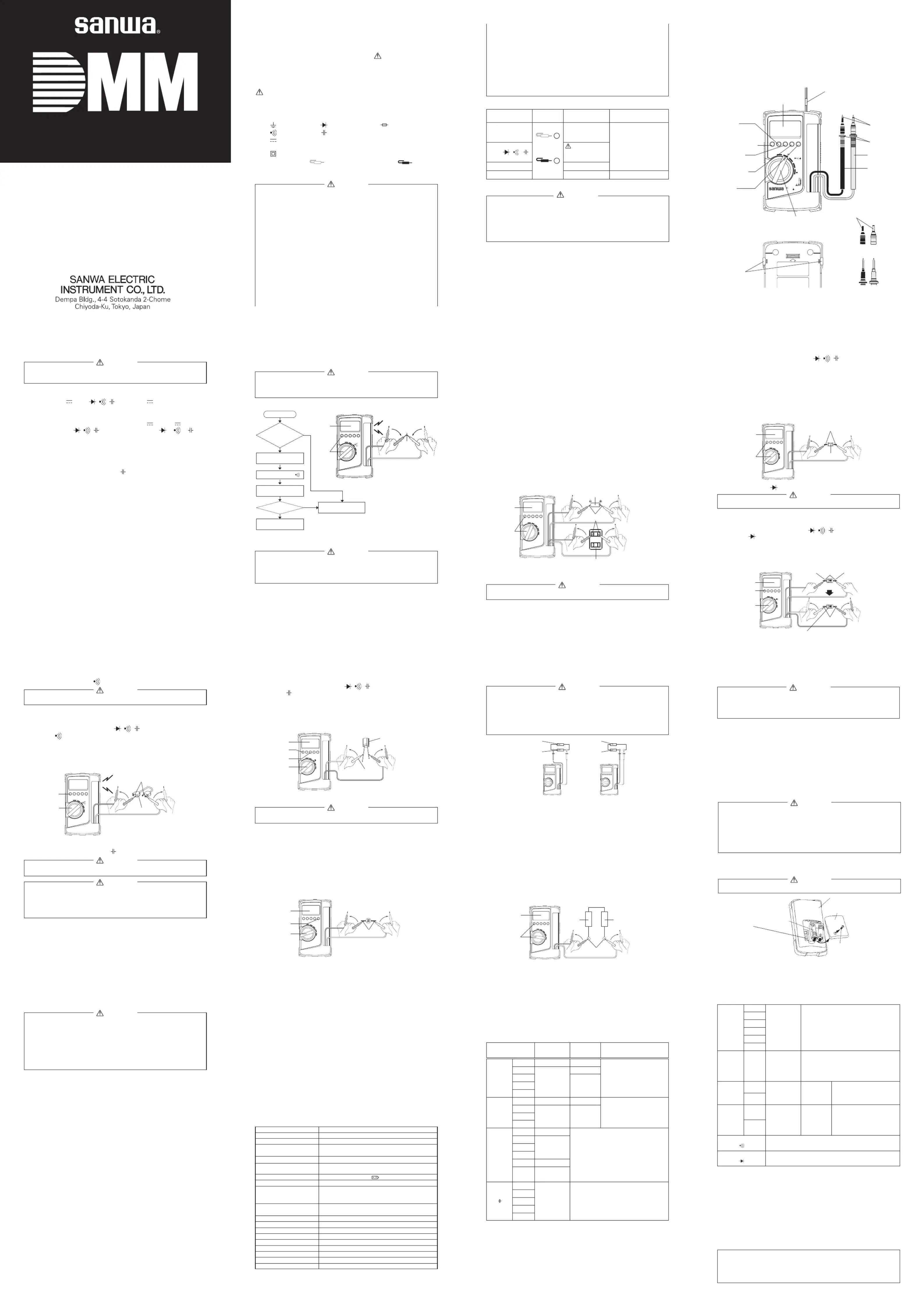
【】3NEME OF COMPONENT UNITS
Multimeter
SELECT button
Stopper
RANGE
hold button
RELATIVE
button
DATA HOLD
button
Hz / %
select button
Test Probe
(Black)
Test Probe
(Red)
POWER switch and FUNCTION switch
Test Pins
Finger Guards
Test Leads
Hand strap
Body Cover
Display
Removable
test pin covers
When not covered
2-2Features
●Sharp contrast LCD with character 17.5 mm high is employed, and unit
symbols are displayed on the screen of the LCD.
●Frequency, capacitance and duty cycle measurement function.
●Attachment body cover is used for protection of the meter and as a tilt
stand.
●The current function is protected by a fuse.
CAUTION
1. Correct measurement may not be performed when using the meter
in the ferromagnetic / intense electric field such as places near a
transformer, a high-current circuit, and a radio.
2. The meter may malfunction or correct measurement may not be
performed when measuring special waveform such as that of the
inverter circuit.
--3
Specyfikacje produktu
| Marka: | Sanwa |
| Kategoria: | multimetr |
| Model: | CD800a |
Potrzebujesz pomocy?
Jeśli potrzebujesz pomocy z Sanwa CD800a, zadaj pytanie poniżej, a inni użytkownicy Ci odpowiedzą
Instrukcje multimetr Sanwa

8 Grudnia 2024
30 Września 2024
30 Września 2024
30 Września 2024
30 Września 2024
30 Września 2024
30 Września 2024
30 Września 2024
30 Września 2024
30 Września 2024
Instrukcje multimetr
Najnowsze instrukcje dla multimetr
3 Kwietnia 2025
3 Kwietnia 2025
3 Kwietnia 2025
3 Kwietnia 2025
3 Kwietnia 2025
3 Kwietnia 2025
3 Kwietnia 2025
28 Marca 2025
26 Marca 2025
14 Marca 2025