Instrukcja obsługi Sanwa PM3
Przeczytaj poniżej 📖 instrukcję obsługi w języku polskim dla Sanwa PM3 (2 stron) w kategorii multimetr. Ta instrukcja była pomocna dla 48 osób i została oceniona przez 8 użytkowników na średnio 4.9 gwiazdek
Strona 1/2
PM3
DIGITAL MULTITESTER
INSTRUCTION MANUAL
SANWA ELECTRIC
INSTRUMENT CO.,LTD.
Dempa Bldg., 4-4 Sotokanda 2-Chome
Chiyoda-ku, Tokyo, Japan
10.
NeveopetestecasexcepwhereplacinbatteriesDonornretng. t
attempt any alteration of original specifications.
11.
Toeydn,ed eensursafetanmaintaiaccuracycalibratancheckth
tester at least once a year.
12.The multimeter restricts in use in indoor.
1-3 Maximum Overload Protection Input
*:AC voltage is regulated by rms valus of sinusoidal wave.
【】2APPLICATION AND FEATURES
2-1 Application
This instrument is portable multimeter designated for measurement
of weak current circuit.
2-2 Features
・This multimeter is very thin type. Body thickness is 8.5 mm.
・Sharp contrast LCD with character 13.6 mm high is employed,
and unit symbols is displayed on the screen of the LCD.
・Addition function: Hz/Duty , Relative and Data Hold.
・Auto power off(15 min.) It is able to cancel it.
・The einstrumenthasbeendesignedinaccordancewithth
safety standard IEC 1010-1.
(
DC/AC 500 V Max. CATII
)
【
3
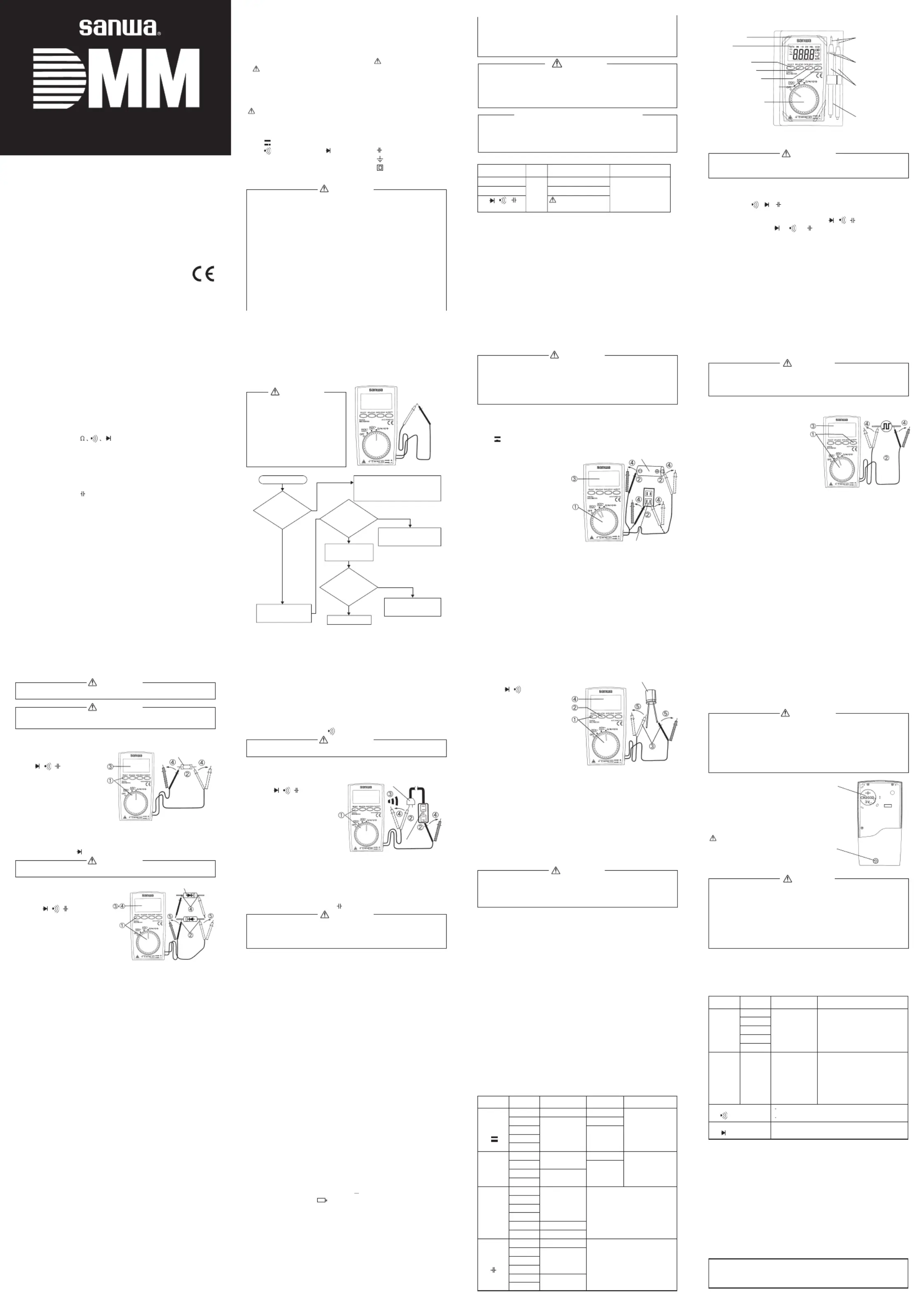
】NAME OF COMPONENT UNITS
【】4DESCRIPTION OF FUNCTIONS
WARNING
Inthecaseofactionorcancelthatfunctionasfollows,dono t
turn the function switch in the condition applied input.
1) Power switch and function switch
Turthiswitcturanofthpoweanselecthfunctionnshtonondferdtesof
DCV, ACV,,,,.Ω
2) Select switch
Thiswitcusefothswitchincasthshsitregof///.IntheΩeofe
mode change as
Ω→→→→Ω.
3) Data hold switch
When this switch is pressed, the data display at that time continues
(DH lights on the display). When the measuring input changes, the
display will not change. When this switch is pressed again, the hold
statusiscanceledyoucanreturntothemeasuringstatus.(DHonthe
display disappears.)
(DATA HOLD function does not work when measuring frequency.)
4
)
Relative measurement switch
(
RELATIVE
)
Suppose that actual value is X1 when REL switch is pressed. Then,
valuX-XdisplayefoactuainpuvaluaftethatEachtimeof1isdrlteXr. e
pressing REL switch,value of X1
is updated. This function is except
the Hz/DUTY measurement mode.
<>In the case of use at the DCV and ACV function
・In the case of canceled, please push the switch again.
・
Thmeasuremenrangfixethrangthpointhatpusheeteisdtoeeinet d
theswitch.Aboutmeasurementafterthis,therangeisfixed. To
returntotheautorange, pleasstomeasuremenoncansetthepted e
function again.
・
Do not measure any signal that exceeds the maximum of current range.
<>In the case of use function
・When“”O.Lis,gdnet.displayedsettinancancellatioarnopossible
・In the case of canceled, please push the switch again.
・
Thresistancmeasuremenrangfixeeeteisdtoeein tthrangthepoin
thapushethswitchAboumeasuremenaftethisthrangetde.ttr,e is
fixed. To return to thmnge, please stop measurement once and
set the function again.
<>In the case of use function
・In the case of canceled, please push the switch again.
・
ThCapacitancmeasuremenautrangmodonlyAftecanceleeetisoee.rd
relative mode, it is possible measurement with the auto range.
5) Hz/DUTY (Frequency/Duty)switch
This switch uses it for the switching of Hz/DUTY. In the case of the
mode change as HzDUTYvoltage measuring modeHz.→→→
●When YitreturnsittothevoltagefunctionaftertheHz/DUT
measurement the range is fixed automatically. (DCV function is
400 mV. ACV function is 4 V.) Please stop measurement once to
cancel the manual range. And please do measurement after the
function is set up again.
6) Auto power off
The power of the meter will automatically turned off after the beep if no operation
isdoneforabout15minutes.Toresetthemeter,pressanybuttonofth e
RELATIVE, DATA HOLD, or Hz/DUTY. To cancel this function, press the SELECT
switch, or change the function switch from the OFF to a desired function while
holding the SELECT switch pressed, and then release the SELECT switch after a
couple of minutes. Set the function switch to OFF when meter is not in use.
【】5MEASUREMENT PROCEDURE
5-1 Start-up Inspection
WARNING
1.
Beetok rsurpre-checthemete
before use.
2.Do not use a damaged meter
and test leads.
3.
Checkcontinuityoftestleads.
4.
When a battery exhaust mark
appearsinthedisplay,replace
the battery with a new one.
*: noteNon-marking may suggest that a battery be exhausted.
5-2-2 Hz/DUTY Measurements
Maximum rating input value 60.00 kHz / 99 %
CAUTION
Thesettingandmeasurement(AtthetimeofACvoltageinput)ofth e
Hz/DUTYarepossibleattheDCVfunctiontoo.However,werecommend
the use in the ACV function.
1) Applications: Measures frequency and duty of any circuit.
2) Measurement procedure
①Set the function switch
at ACV function. Push the
Hz/DUTY switch one time,
and select the Hz function.
(The unit display is Hz display.)
In the case of duty measurement,
then push the Hz/DUTY switch
one more time, and select
the duty function.
(The unit display is % display.)
②Apply the red and black test pins to the circuit to measure.
③Read the value on the display.
④Aft men r t and ck test omerasuremet,emoveheredblapinsfr
the circuit measured.
●With wmeasuringterminalsdisconnected,displaymayoverflo
or value may unsteadily fluctuate. There are not malfunctions.
●Input sensitivity varies according to frequency and wave-form.
●Please refer to 8-2 Measurement Range and Accuracy.
●It is only auto range mode.
●When YitreturnsittothevoltagefunctionaftertheHz/DUT
measurement the range is fixed automatically. (DCV function is
400 mV. ACV function is 4 V.) Please stop measurement once to
cancelthemanualrange.Andpleasedomeasurementafte r
the function is set up again.
●DATA HOLD function does not work when measuring frequency.
●The ometercannotmeasurefrequencythatdoesnotgotoandfr
O voltage.
Safety: EN61010-1, EN61010-2-030, EN61010-2-033, EN61010-031
≦・IIDCAC 500 V: Designed to protection Class
requirement of IEC 1010-1, Pollution degree II.
EMC : EN61326-1: 2013
RoHS: EN50581
Measurement Category(Overvoltage Category) II
:Local Level
Appliance
Portable Equipment
8-2 Measurement Range and Accuracy
Accuracyassurance range:235 80±℃ %RHMAX.Nocondensation.
【】1SAFETY PRECAUTIONS
: Before use,read the following safety precautions
ThisinstructionmanualexplainshowtouseyourmultimeterPM 3
safely. Before use,please read this manual thoroughly. After reading it,
keep it together with the product for reference to it when necessary.
The instruction given under the heading “”WARNING
“”CAUTIONmust be foow to prevent acent rn orlledcidalbu
electrical shock.
1-1 Explanation of Warning Symbols
The meaning of the symbols used in this manual and attached to
the product is as follows.
:Very important instruction for safe use.
・The towarningmessagesareintendedtopreventaccidents
operating personnel such as burn and electrical shock.
・
The caution messages are intended to prevent damage to the instrument.
DCV DC voltage ACV:~:Ω:AC voltage Resistance
:::Buzzer DiodeCapacitance
HzFrequencyDUTYDuty cycleGround:::
+:-::PlusMinusDouble insulation
1-2 Warning Instruction for safe use
WARNING
To ensure that the meter is used safely, be sure to observe the
instruction when using the instrument.
1. Never use meter on the electric circuit that exceed 3.6 kVA.
2. Pay special attention when measuring the voltage AC 33 Vrms
(46.7 V peak) or DC 70 V or more to avoid injury.
3.
Never apply an input signal exceeding the maximum rating input value.
4.
Neveusmetefomeasurinthlinconnectewitequipmenrerrgeedht
(i.e. motors) that generates induced or surge voltage since it may
exceed the maximum allowable voltage.
5.
Neveusmetethmetetesleadardamagebrokenreriferortsedor.
6. Never use uncased meter.
7.
Alwayskeepyourfingersbehindthefingerguardson theprobe
when making measurements.
8.
Beetotetsmet.surdisconnecthtespinfrothcircuiwhen changing the function
9. Never use meter with wet hands or in a damp environment.
Function
DCV (Hz/ DUTY)
ACV (Hz/DUTY)
Ω///
Input
+, -
Maximum rating
Input value
DC 500 V
AC 500 V
Voltage and current
Input prohibited
Maximum overload
Protection voltage
DC 500 V, AC 500 V or
Peak Max.700 V
Case holder
Display
Select switch
Relative switch
Data hold switch
Hz/DUTY select
switch
Power switch and
function switch
Test pins
Finger
guards
Test probe
(Red and Black)
Test leads
(TL-PM3)
5-2 Voltage, Hz/DUTY measurement
WARNING
1.
Never apply an input signal exceeding the maximum rating input value.
2.
Be sure to disconnect the test pins from the circuit when changing
the function.
3.
Always keep your fingers behind the finger guards on the probe
when making measurements.
5-2-1 Voltage Measurement (DCV,ACV)
Maximum rating input value DC/AC 500 V
1) Applications
DCV : Measures batteries and DC circuits.
ACV : Measures sine-wave AC voltage as lighting voltages.~
2) Measurement procedure
①Set the function switch
“”“”DCVorACVfunction.
②Apply the black test pin
to the negative potential
side of the circuit to measure
and the red test pin to the
positive potential side.
③Read the value on the display.
④
After measurement, remove
threanblactespinfroeddktsm
the circuit measured.
●The display fluctuates when
the test leads are removed. This is not malfunction.
●
Since this instrument employs the means value system for its AC
voltagemeasurementcircuitACwaveformotherthansinewav , e
may cause error.
●
In the AC 4 V ranges a figure of about 39 conuts will stay on even if~
no input signal is present.
●The accuracy guaranteed frequency range is 40 Hz to 400 Hz.
<DCV>
<ACV>
2) Repair during the warranty period:
Thefailedmeterwillberepairedinaccordancewithth e
conditions stipulated in 7-1 Warranty and Provision.
3) Repair after the warranty period has expired:
Insomecases,repairandtransportationcostmaybecom e
higherthanthepriceoftheproduct.PleasecontactSanw a
authorized agent / service provider in advance.
The minimum retention period of service functional parts is 6
years after the discontinuation of manufacture. This retention
period is the repair warranty period. Please note, however, if
suchfunctionalpartsbecomeunavailableforreasons of
discontinuation of manufacture, etc., the retention period may
become shorter accordingly.
4) Precautions when sending the product to be repaired:
Toensurethesafetyoftheproductduringtransportation ,
placetheproductinboxthatislargerthantheproduct a 5
timormoreinvolumefillcushionteialslles and mar fuy and
thenclearlymark“RepairProductEnclosed”onthebo x
surface. The cost of sending and returning the product shall be
borne by the customer.
7-3 SANWA Website
http://www.sanwa-meter.co.jp
E-mail: exp_sales@sanwa-meter.co.jp
【】8SPECIFICATIONS
8-1 General Specifications
Measuring Method: ΔΣ
Display: 4000 counts max.
Range selection: Auto ranges
Over display:“”O.Ldisplay
Polarity: Automatic selection (only“
”is displayed)
Low Battery Indication:
Sampling rate: Approx. 3 times/sec.
Accuracy assurance temperature /humidity range:
235 80 %RH max. No condensation.±℃
Operating temperature/humidity range:
040 80 %RH max. No condensation.~℃
Storage temperature/humidity range:
-1050 70 %RH max. No condensation.~℃
EnvironmentaconditionOperatinaltitudl:ge,<2000 m
Pollutiodegreen2 Indoor use only
Power supply: Coin type lithium battery CR2032 (3 V), 1 pcs.
Power consumption: Approx.6 mW TYP. (at DCV)
Battery life: Approx.150 hours at DCV
Dimension and mass:108()56()11.5()mm Approx.50 gH×W×D
Accessories: Instruction manual 1, Case holder 1
Function
DCV
ACV
~
Ω
CAP.
Range
400.0 mV
4.000 V
40.00 V
400.0 V
500 V
4.000 V
40.00 V
400.0 V
500 V
400.0 Ω
4.000 kΩ
40.00 kΩ
400.0 kΩ
4.000 MΩ
40.00 MΩ
5.000 nF
50.00 nF
500.0 nF
5.000 μF
50.00 μF
200.0 μF
Accuracy
±(0.7 %rdg+3dgt)
±(1.3 %rdg+3dgt)
±
(2.3 %rdg+10dgt)
±(2.3 %rdg+5dgt)
±(2.0 %rdg+5dgt)
±(5.0 %rdg+5dgt)
±(10 %rdg+5dgt)
-------------------------------------
±
(5.0 %rdg+10dgt)
±
(10 %rdg+15dgt)
Input
Resistance
≧100 MΩ
Approx.11 MΩ
Approx.10 MΩ
Approx.11 MΩ
Approx.10 MΩ
Remarks
*Acurainccy the
case of sine wave.
*Frequency range:
40z~400 H
*Open voltage: Approx. 0.4 V
*The measuring current changes
according to the resistance
measure.
*Accuracywasmeasure d
aftercancelingdisplayvalu e
by relative key.
YES
YES
YES
NO
NO
Main unit
and test leads
damaged?
Is a battery
Exhaustion mark is
on?(*note)
Display shows
000.01.0?~
Short the RED and
BLACK test pin
Set the function
switch to.Ω
Replace the battery.
Please check again
Stop using it and have
it repaired.
To avoid danger of shock hazard,
do not use multimeter with
damage and repair the meter.
End of pre-check
START
NO
Accuracy in the case of sine wave.
●Do not use the tester near places where strong electromagnetic
waves and trance are generated or strong electrical voltages are
generated.
◎Accuracy calculation
For exampleMeasurement DCmV:
Displayed value100.0 mV:
Accuracy400 mV range :・・・・±(0.7 %rdg+3dgt)
Error (100[mV]0.7 %+3[dgt] )=1.0[mV] :±×±
True value :
100.0[mV]±
1.0[mV](In a range of 99.0~101.0 mV)
*3[dgt] in the 400 mV range corresponds to 0.3 mV.
Specifications and external appearance of the product
described above may be revised for modification without
prior notice.
Buzzer sounds at less than 10
~
120 Ω
Open voltage: Approx. 0.4 V
Open voltage: Approx 1.5 V
Function
Hz
DUTY
BUZZER
DIODE
Range
9.999 Hz
99.99 Hz
999.9 Hz
9.999 kHz
60.00 kHz
0.1
~
99 %
Accuracy
±(0.7 %rdg+5dgt)
-------------------------------------
Remarks
*Accuracyinthecaseofsin e
wave.
9.999 H9.999 kHz: 10 Vrmz~s~.250 Vrms
60.00 kHz: 40 Vrms
~
100 Vrms.
Aboutinputsensitivityan d
fruraceqency chateritics:
(Square waveDUTY 50 % input)
2.5 V 0 to peak input:
≧
1 kHz
6 V 0 to peak input:
≧
1z0 kH
40 V 0 to peak input:
≧
60 kHz
●Make sure that the test leads are not cut, referring to the section.
6-2 Calibration
Thedealermayconductthecalibrationandinspection.Formor e
information, please contact the dealer.
6-3 How to Replace Battery
WARNING
1.
If the rear case is removed with input applied to the input terminals,
you may get electrical shock. Before starting the work, always
make sure that no inputs is applied.
2.
Be sure to use the fuse is same rating so as to ensure safety and
performance of tester.
3.
When operators remove the rear case, do not touch the internal
parts or wire with hand.
<>How to replace the battery
①Remove the rear case
screw with a screwdriver.
②Remove the rear case.
③Take out the battery and replace it with a
new one.
④Attach the rear case and fix it with the screw.
CAUTION
Set a battery with its polarities
facing in the correct directions.
6-4 Storage
CAUTION
1.
The panel and the case are not resistant to volatile solvent and
must not be cleaned with thinner or alcohol. For cleaning, use
dry, soft cloth and wipe it lightly.
2.
The panel and the case are not resistant to heat. Do not place
the instrument near heat-generating devices (such as a soldering iron)
3.
Do not store the instrument in a place where it may be subjected
to vibration or from where it may fall.
4.
For storing the instrument, avoid hot, cold or humid places or places.
Under direct sunlight or where condensation is anticipated.
Following the above instructions, store the instrument in good environment.
Coin type
lithium battery
CR2032
Screw
2) Measurement procedure
①Set the function switch
at ///nFfunctionΩ
and select the function
by SELECT switch.
②Press the RELATIVE
switch to make display
show 00.00 nF. (The“”REL
mark illuminates in the upper
right area of the display.)
③Apply the black red test pin
to capacitor.
④Read the value on the display.
⑤After mmeasurement,removetheredandblacktestpinsfro
the circuit measured.
●For measurement of 100 nF or below, the display will not stabilize
due to the influence of ambient noise and floating capacity.
●Necessarily spleasedischargetheelectricchargethatwa
charged to the condenser before measurement.
●As the capacitance increases, the measuring time becomes longer.
(Example: approx. 5 sec. at 10 µ. Approx.45 sec. at 150 µF.)
【】6MAINTENANCE
WARNING
1.
Thissectionisveryimportantforsafety.Readandunderstandthefollowin g
instruction fully and maintain your instrument properly.
2.
The instrument must be calibrated and inspected at least once a year to
maintain the safety and accuracy.
6-1 Maintenance and inspection
1. Appearance:Is the appearance not damaged by falling?
Capacitor
-+
Table tap
Plug
④Replace etheredandblacktestpins,makesurethatth
displays the same as that when the test leads are released.
⑤A m lse r bl t pi fmftereasurent,mereeatheedandackestnsro
the object measured.
Judgment:Whethitemanarnormalthdiodnes③d④e,ee.is good
●The input terminals release voltage is about 1.5 V.
5-5 Checking Continuity ( )
WARNING
Never apply voltage to the input terminal.
1)
ApplicationCheckinthcontinuitwirinanselectinwires:geyofgdg.
2) Measurement procedure
①Set the function switch
at ///functionΩ
and select the function
by SELECT switch.
②Apply the red and black
test pins to a circuit or
conductor to measure.
③The continuity can be
judged by whether the
buzzer sounds or not.
④A m lse r bl t pi fmftereasurent,mereeatheedandackestnsro
the object measured.
●The buzzer sounds when the resistance in a circuit to measure
is less than about 10 100 Ω~Ω
●The input terminals release voltage is about 0.4 V.
5-6 Capacity Measurement ()
WARNING
1.Never apply voltage to the input terminal.
2.This is not suitable for measurement of electrolytic condenser
such as a large leakage condenser.
1) Application: Measures capacitance of capacity.
ー 5ーー 4ー
01ーー 9ーーー11 ーー8 ー
ーー 51ーー 41ーー 31
ー 7ーー 6ー
ー1 ーー3 ー
【】7AFTER-SALE SERVICE
7-1 Warranty and Provision
Sanwaofferscomprehensivewarrantyservicestoitsend-user s
and to its product resellers. Under Sanwa's general warranty policy,
eachinstrumentiswarrantedtobefreefromdefects in
workmanship or material under normal use for the period of one (1)
year from the date of purchase.
Thiswarrantypolicyisvalidwithinthecountryofpurchaseonly ,
and applied only to the product purchased from Sanwa authorized
agent or distributor.
Sanwa reserves the right to inspect all warranty claims to determine
theextenttowhichthewarrantypolicyshallapply.Thiswarrant y
shallnotapplytodisposablesbatteries,oranyproductorparts ,
which have been subject to one of the following causes:
1.failureduetoimproperhandlingorusethatdeviatesfro A m
the instruction manual.
2.failureduetoinadequaterepairormodificationbypeopl A e
other than Sanwa service personnel.
3. A failure due to causes not attributable to this product such as
fire, flood and other natural disaster.
4. Non-operation due to a discharged battery.
5.failureordamageduetotransportation,relocation A or
dropping after the purchase.
7-2 Repair
Cto are asd pvide e o ia nusmersketorothfollwingnformtionwhe
requesting services:
1. Customer name, address, and contact information
2. Description of problem
3. Description of product configuration
4. Model Number
5. Product Serial Number
6. Proof of Date-of-Purchase
7. Where you purchased the product
PleasecontactSanwaauthorizedagentdistributorservic / / e
provider,listedinourwebsite,inyourcountrywithabov e
information.AninstrumentsenttoSanwaagentdistributo / / r
without those information will be returned to the customer.
Note:
1) Prior to requesting repair, please check the following:
Cacity of t , polay of station andaphebuilint-batteryritinlla
discontinuity of the test leads.
ー12 ー
1. eCorrectmeasurementmaynotbeperformedwhenusingth
meter in the ferromagnetic / intense electric field such as places
near a transformer, a high-current circuit, and a radio.
2.
Themetermaymalfunctionorcorrectmeasurementmaynotbeperforme d
when measuring special waveform such as that of the inverter circuit.
CAUTION
A battery for monitoring is preinstalled before shipping therefore it may
run down sooner than the battery life specified in the instruction manual.
●
The
“
battery for monitoring
”
is a battery to inspect the functions
and specifications of the product.
Factory-preinstalled built-in battery
●This digital multimeter has 4000(5000) counts max. display, however,
its range may change even less than 4000(5000) counts depending
on the using function or the measuring range.
5-3 Resistance Measurement ()Ω
WARNING
Never apply voltage to the input terminal.
CAUTION
Thereadingmayvarybecauseofexternalinductancewhe n
measuring high resistance value.
1)
Application:Resistanceofresistorsandcircuitsaremeasured.
2) Measuring ranges:400 Ω~ 40 M(6 range)Ω
3) Measurement procedure
①Set the function switch at
Ω/ / / function.
②Apply the black red test
pin to measured circuit.
③Read the value on the
display.
④After measurement, remove
the red and black test pins
from the circuit measured.
●If emeasurementislikelytobeinfluencedbynoise,shieldth
object to measure with negative potential (test lead black).
●The input terminals release voltage is about 0.4 V.
5-4 Testing Diode ()
WARNING
Never apply voltage to the input terminal.
1) Application: The quality of diodes is tested.
2) Measurement procedure
①Set the function switch
at / / / functionΩ
and select the function
by SELECT switch.
②Apply the black test pin to
the cathode of the diode and
the red test pin to the anode.
③Make sure that the display
shows a diode forward voltage drop.
Resistor
Diode
Test leads:Are you having the problem with “the test leads are damaged,
and the cable core and white coating inside of the test leads are exposed”?
(We use double insulation test leads. If you could see the test
leads as above condition, you need to change the new one).
Please do not use as it is, if applicable, of the above items.
Please have it serviced.
2.
Specyfikacje produktu
| Marka: | Sanwa |
| Kategoria: | multimetr |
| Model: | PM3 |
Potrzebujesz pomocy?
Jeśli potrzebujesz pomocy z Sanwa PM3, zadaj pytanie poniżej, a inni użytkownicy Ci odpowiedzą
Instrukcje multimetr Sanwa

8 Grudnia 2024
30 Września 2024
30 Września 2024
30 Września 2024
30 Września 2024
30 Września 2024
30 Września 2024
30 Września 2024
30 Września 2024
30 Września 2024
Instrukcje multimetr
Najnowsze instrukcje dla multimetr
3 Kwietnia 2025
3 Kwietnia 2025
3 Kwietnia 2025
3 Kwietnia 2025
3 Kwietnia 2025
3 Kwietnia 2025
3 Kwietnia 2025
28 Marca 2025
26 Marca 2025
14 Marca 2025