Instrukcja obsługi Elan Dombard 84320
Przeczytaj poniżej 📖 instrukcję obsługi w języku polskim dla Elan Dombard 84320 (8 stron) w kategorii Ulga. Ta instrukcja była pomocna dla 15 osób i została oceniona przez 8 użytkowników na średnio 4.7 gwiazdek
Strona 1/8
For warranty informaon please visit: kichler.com/warranty
1) Remove mounng pan[E] from main body[B] by
unscrewing three (3) countersunk mounng screws[G]
from side of main body. Retain screws for re-aaching
main body to mounng pan.
2) Find the appropriate threaded holes on mounng
strap[A] that align with hole distance in mounng
pan[E]. Thread mounng screws[F] into threaded holes
of mounng strap. Mounng screws should be threaded
into mounng strap approximately 3mm (1/8") and from
the side of mounng strap opposite the outlet box[C].
Fixture Diagram
Parts List
Cauons
CAUTION – RISK OF SHOCK –
Disconnect Power at the main circuit breaker panel or main
fusebox before starng and during the installaon.
WARNING:
This xture is intended for installaon in accordance
with the Naonal Electrical Code (NEC) and all local code
specicaons. If you are not familiar with code requirements,
installaon by a cered electrician is recommended.
DIMMING:
This LED xture is compable with most standard
incandescent dimmers, LED dimmers, and electronic low
voltage dimmers.
For opmal performance, an electronic low voltage dimmer
should be used.
See kichler.com/dimming for a list of compable dimmers.
CLEANING:
• Always be certain that electric current is turned o before
cleaning.
• Only a so damp cloth should be used. Harsh cleaning
products may damage the nish.
Installaon Instrucons
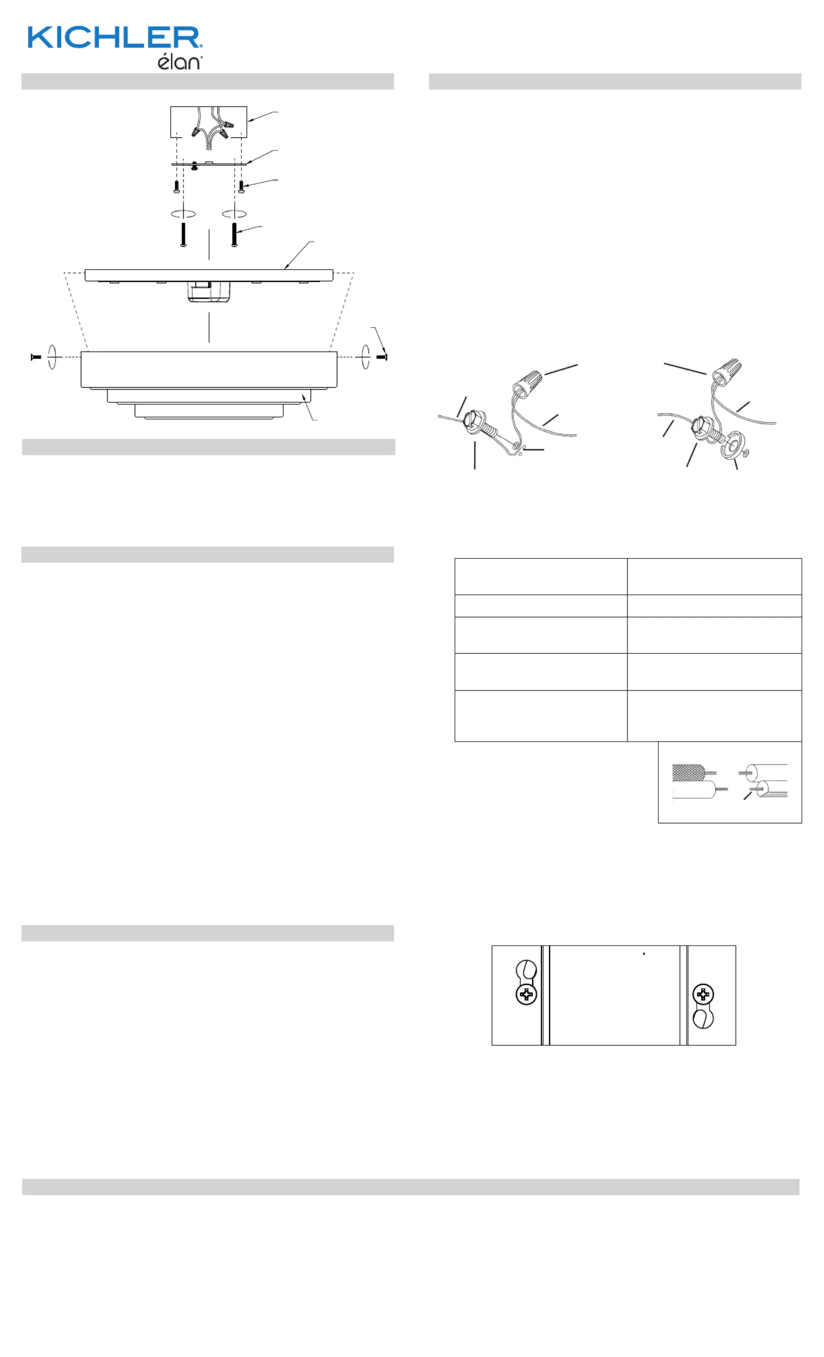
[A] Mounting
Strap
[B] Main Body
[C] Outlet Box
[D] Strap
Mounting
Screw
[E] Mounting
Pan
[F] Mounting
Screw
[G] Countersunk
Mounting
Screw
3) Aach mounng strap to outlet box using the [A] [C]
strap mounng screws . Mounng strap can be [D]
adjusted to suit posion of xture.
4) Grounding instrucons: (See Illus. a or b).
a) On xtures where mounng strap is provided with a
hole and two raised dimples, wrap ground wire from
outlet box around green ground screw, and thread
into hole.
b) On xtures where a cupped washer is provided,
aach ground wire from outlet box under cupped
washer and green ground screw, and thread into
mounng strap.
If xture is provided with ground wire, connect xture
ground wire to outlet box ground wire with wire
connector aer following the above steps. Never connect
ground wire to black or white power supply wires.
5) Make wire connecons. Reference chart below for
correct connecons and wire accordingly.
Connect Black or Red
Supply Wire to:
Connect White Supply
Wire to:
Black White
*Parallel cord (round &
smooth)
*Parallel cord (square &
ridged)
Clear, Brown, Gold or
Black without Tracer
Clear, Brown, Gold or Black
with Tracer
Insulated wire (other
than green) with copper
conductor
Insulated wire (other
than green) with silver
conductor
*Note: When parallel wire (SPT
1 & SPT 2) are used. The neutral
wire is square shaped or ridged
and the other wire will be round
in shape or smooth (See illus.) Neutral Wire
6) Raise mounng pan to ceiling, carefully passing over [E]
heads of mounng screws parally threaded into [F]
mounng strap.
7) Rotate the mounng pan to secure and ghten mounng
screws[F] up against mounng pan to secure pan to
ceiling. Mounng screws should be ghtened in the
keyholes as shown:
GREEN GROUND
SCREW
CUPPED
WASHER
OUTLET BOX
GROUND
FIXTURE
GROUND
DIMPLES
WIRE CONNECTOR
OUTLET BOX
GROUND
GREEN GROUND
SCREW
FIXTURE
GROUND
a
b
Installaon Instrucons (connued)
This device complies with part 15 of the FCC Rules. Operaon is subject to the following two
condions:
1) This device may not cause harmful interference, and
2) This device must accept any interference received, including interference that may cause
undesired operaon.
Note: This equipment has been tested and found to comply with the limits for a Class B digital
device, pursuant to part 15 of the FCC Rules. These limits are designed to provide reasonable
protecon against harmful interference in a residenal installaon. This equipment generates,
uses and can radiate radio frequency energy and, if not installed and used in accordance with
the instrucons, may cause harmful interference to radio communicaons. However, there is
no guarantee that interference will not occur in a parcular installaon. If this equipment does
cause harmful interference to radio or television recepon, which can be determined by turning
the equipment o and on, the user is encouraged to try to correct the interference by one or
more of the following measures:
• Reorient or relocate the receiving antenna.
• Increase the separaon between the equipment and receiver.
• Connect the equipment into an outlet on a circuit dierent from that to which the
receiver is connected.
• Consult the dealer or an experienced radio/TV technician for help.
FCC Informaon:
IS-84320-US
We’re here to help 866-558-5706
Hrs: M-F 9am to 5pm EST
REV 22-APR-2021
8) Raise main body[B] up over mounng pan , carefully [E]
aligning the mounng screw holes on the side of the
body with the holes on the side of the mounng pan.
9) Secure main body to mounng pan using countersunk
mounng screws[G] previously removed from main
body.
C
D
E
F
B
G
A
Specyfikacje produktu
| Marka: | Elan |
| Kategoria: | Ulga |
| Model: | Dombard 84320 |
Potrzebujesz pomocy?
Jeśli potrzebujesz pomocy z Elan Dombard 84320, zadaj pytanie poniżej, a inni użytkownicy Ci odpowiedzą
Instrukcje Ulga Elan

10 Stycznia 2025

12 Grudnia 2024

12 Grudnia 2024

12 Grudnia 2024

12 Grudnia 2024

12 Grudnia 2024

12 Grudnia 2024

12 Grudnia 2024

12 Grudnia 2024

12 Grudnia 2024
Instrukcje Ulga
- Futurelight
- Blumfeldt
- Fluval
- OttLite
- 9.solutions
- Hama
- Heitronic
- Perel
- Monacor
- Brilliant
- Ideen Welt
- Hinkley Lighting
- Godox
- OneConcept
- Astera
Najnowsze instrukcje dla Ulga

9 Kwietnia 2025

8 Kwietnia 2025

8 Kwietnia 2025

8 Kwietnia 2025

8 Kwietnia 2025

7 Kwietnia 2025

5 Kwietnia 2025

5 Kwietnia 2025

5 Kwietnia 2025

5 Kwietnia 2025