Instrukcja obsługi Klein Tools CL810
Klein Tools
Sprzęt pomiarowy
CL810
Przeczytaj poniżej 📖 instrukcję obsługi w języku polskim dla Klein Tools CL810 (27 stron) w kategorii Sprzęt pomiarowy. Ta instrukcja była pomocna dla 38 osób i została oceniona przez 19.5 użytkowników na średnio 4.9 gwiazdek
Strona 1/27

INSTRUCTION MANUAL
ENGLISH
FRANÇAIS p. 33
ESPAÑOL pg. 17
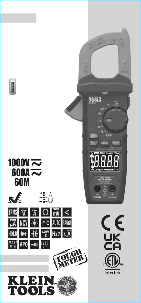
600A AC/DC Auto-Ranging
Digital Clamp Meter
True RMS
Measurement
Technology
• NON-CONTACT
VOLTAGE TESTER
• LOW IMPEDANCE
• DATA & RANGE HOLD
• AUDIBLE CONTINUITY
• DIODE TEST
• CAPACITANCE & FREQUENCY
• TRANSFLECTIVE
REVERSE-CONTRAST DISPLAY
• LIGHTED DIAL
1000V
60M
Ω
600A
CL810
2
m
IP40
-40° – 1832°F
(-40° – 1000°C)
5000573
CAT IV
600V
CAT III
1000V

2 3
GENERAL SPECIFICATIONS
Klein Tools CL810 is an automatically ranging true root mean square
(TRMS) digital clamp-meter that measures AC/DC current via the clamp,
measures AC/DC voltage, resistance, continuity, frequency, inrush,
capacitance, and tests diodes via test-leads, and temperature via a
thermocouple probe. It also features a Low Impedance (LoZ) mode for
identifying and eliminating ghost or stray voltages, transflective reverse-
contrast display, and lighted dial.
• Environment: Indoor: Do not expose to moisture, rain or snow.
• Operating Altitude: 6562 ft. (2000m)
• Relative Humidity: <80% non-condensing
• Operating Temp: 32° to 122°F (0° to 50°C)
• Storage Temp: 14° to 140°F (-10° to 60°C)
• Accuracy: Values stated at 65° to 83°F (18° to 28°C)
• Temp Coefcient: 0.1 × (Quoted Accuracy) per °C above 28°C
or below 18°C, corrections are required when ambient working
temp is outside of Accuracy Temp range
• Auto Power-Off (APO): After 5 minutes of inactivity (unless
disabled)
• Dimensions: 9.06" × 3.47" × 1.65" (230 × 88 × 42 mm)
• Weight: 13 oz. (369 g) including batteries
• Calibration: Accurate for one year
• Standards:
IEC EN 61010-1, 61010-2-032.
Conforms to: UL STD 61010-1, 61010-2-032.
Certied to: CSA STD C22.2 #61010-1, 61010-2-032.
• Pollution degree: 2
• Accuracy: ± (% of reading + # of least significant digits)
• Drop Protection: 6.6 ft. (2m)
• Safety Rating: CAT IV 600V, CAT III 1000V, Class 2,
Double insulation
CAT III: Measurement category III is applicable to test and
measuring circuits connected to the distribution part of the
building’s low-voltage MAINS installation.
CAT IV: Measurement category IV is applicable to test and
measuring circuits connected at the source of the building’s
low-voltage MAINS installation.
• Electromagnetic Environment: IEC EN 61326-1. This
equipment meets requirements for use in basic and controlled
electromagnetic environments like residential properties,
business premises, and light-industrial locations.
Specifications subject to change.
ELECTRICAL SPECIFICATIONS
Function Range Resolution Accuracy LoZ Accuracy
AC
Voltage
(V AC)
600mV 0.1mV ±(1.8% + 8 digits)
±(2.5% + 8
digits)
6.000V 1mV
±(1.0% + 3 digits)60.00V 10mV
600.0V 100mV
1000V 1V ±(1.2% + 5 digits)
DC
Voltage
(V DC)
600mV 0.1mV
±(0.5% + 5 digits)
±(2.0% + 5
digits)
6.000V 1mV
60.00V 10mV
600.0V 100mV ±(0.8% + 3 digits)
1000V 1V ±(1.0% + 3 digits)
Input Impedance: 10MΩ Frequency Range: 50 to 400Hz
Maximum Input: 1000V AC RMS or 1000V DC
NOTE: All AC voltage ranges are specified from 5% to 100% of range.
AC Current
(A AC)
60.00A 10mA ±(2.0% + 8 digits)
600.0A 100mA ±(2.0% + 5 digits)
DC Current
(A DC)
60.00A 10mA ±(2.0% + 8 digits)
600.0A 100mA ±(2.0% + 5 digits)
Frequency Range: 50 to 60Hz
DC
Microamps
(DC µ)
200.0µA 0.1µA ±(1.0% + 5 digits)
Maximum Input: 1000V AC RMS or 1000V DC
Function Range Resolution Accuracy
Resistance
600.0Ω 0.1Ω
±(1.2% + 5 digits)
6.000kΩ 1Ω
60.00kΩ 0.01kΩ
600.0kΩ 0.1kΩ
6.000MΩ 1kΩ
60.00MΩ 10kΩ ±(2.0% + 10 digits)
Maximum Input: 1000V AC RMS or 1000V DC
Capacitance
60.00nF 0.01nF ±(3.5% + 10 digits)
600.0nF 0.1nF
±(3.0% + 5 digits)
6.000µF 0.001µF
60.00µF 0.01µF
600.0µF 0.1µF
6000µF 1µF ±(3.5% + 5 digits)
Maximum Input: 1000V AC RMS or 1000V DC
Temperature
(Fahrenheit)
-40° to 10°F
1
°F
±(1.2% + 7
°F
)
11° to 1832°F
±(1.2% + 6
°F
)
Temperature
(Celsius)
-40° to -12°C
1
°C
±(1.2% + 4
°C
)
-11° to 1000°C
±(1.3% + 3
°C
)
ENGLISH
5000573

4 5
ELECTRICAL SPECIFICATIONS
Function Range Resolution Accuracy
Frequency
(Auto-
Ranging)
1.000Hz to 9.999Hz 0.001Hz
±(1.0% + 5 digits)
99.99Hz 0.01Hz
999.9Hz 0.1Hz
9.999kHz 1Hz
99.99kHz 10Hz
500.00kHz 100Hz
Sensitivity: >2V to 220V RMS
Maximum Input: 1000V AC RMS or 1000V DC
Duty Cycle
1.0% to 99.9%
0.1%
±(1.2% + 2 digits)
Pulse width: >100µs, <100ms Frequency width: 5Hz to 10kHz
Sensitivity: >2V to 220V RMS Maximum Input: 1000V DC or 1000V AC RMS
Inrush
Current
600.0A 100mA ±(3.0% + 8 digits)
Frequency Range: 50 to 60Hz Detection Range: >2A
OTHER MEASUREMENT APPLICATIONS
Maximum Input: 1000V AC RMS or 1000V DC
• Diode Test: Max. 1.5mA, open circuit voltage ~3.2V DC
• Continuity Check: Audible signal <50Ω, test current <1.5mA
• Sampling Frequency: 4 samples per second
• Low Impedence (Low Z): Input impedence >3kΩ,
Max input 1000V AC RMS or 1000V DC RMS
• Auto Power-Off: After ~5 minutes of inactivity
• Overload: "OL" indicated on display, overload protection 1000V in all settings
• Polarity: "-" on display indicates negative polarity
• Display: 3-5/6 digit, 6000 Count LCD
ENGLISH
WARNINGS - GENERAL
To ensure safe operation and service of the meter, follow these instructions.
Failure to observe these warnings can result in severe injury or death.
• Before each use verify meter operation by measuring a known voltage
or current.
• Never use the meter on a circuit with voltages that exceed the category
based rating of this meter.
• Do not use the meter during electrical storms or in wet weather.
• Do not use the meter or test leads if they appear to be damaged.
• Use only with CAT III 1000V/CAT IV 600V rated test leads or better.
• Ensure meter leads are fully seated, and keep fingers away from the
metal probe contacts when making measurements.
• Use caution when working with voltages above 25V AC RMS or 60V DC.
Such voltages pose a shock hazard.
• To avoid false readings that can lead to electrical shock, replace batteries
when a low battery indicator appears.
• Do not attempt to measure resistance or continuity on a live circuit.
• Always adhere to local and national safety codes. Use personal protective
equipment to prevent shock and arc blast injury where hazardous live
conductors are exposed.
• To avoid risk of electric shock, disconnect leads from any voltage source
before removing battery door.
• To avoid risk of electric shock, do not operate meter while battery door is removed.
WARNINGS - NCV FUNCTION
• When NCV Function is initiated, a blinking or steady red glow and an audible
beep indicate voltage present, and the screen will display the corresponding
sensitivity level (1 to 4 bars) when voltage is detected. If no indication, voltage
could still be present.
• Before and after each use of the NCVT, verify operation by testing a known
working circuit that is within the rating of this unit.
• Never assume neutral or ground wires are de-energized. Neutrals in multi-wire
branch circuits may be energized when disconnected and must be retested
before handling.
• The NCV tester WILL NOT detect voltage if:
• The wire is shielded.
• The
operator is not grounded or is otherwise isolated from an effective earth ground.
• The voltage is DC.
• The NCV tester MAY NOT detect voltage if:
• The user is not holding the tester.
• The user is insulated from the tester with a glove or other materials.
• The wire is partially buried or in a grounded metal conduit.
• The tester is at a distance from the voltage source.
• The field created by the voltage source is blocked, dampened, or otherwise
interfered with.
• The frequency of the voltage is not a perfect sine wave between 50 and 60Hz.
• The tester is outside of operation conditions (listed in Specifications section).
• Operation may be affected by differences in socket design and insulation
thickness and type; tester may not be compatible with some types of standard
or tamper resistant (TR) electrical outlets.
• Do not apply to uninsulated hazardous live conductors.
• Detection above 50V is specified under “normal” conditions as specified below.
The tester may detect at a different threshold at different conditions, or may not
detect at all unless:
• The
tip of the tester is within 0.25" of an AC voltage source radiating unimpeded.
• The user is holding the body of the tester with his or her bare hand.
• The user is standing on or connected to earth ground.
• The air humidity is nominal (50% relative humidity).
• The tester is held still.
Specyfikacje produktu
Marka: | Klein Tools |
Kategoria: | Sprzęt pomiarowy |
Model: | CL810 |
Potrzebujesz pomocy?
Jeśli potrzebujesz pomocy z Klein Tools CL810, zadaj pytanie poniżej, a inni użytkownicy Ci odpowiedzą
Instrukcje Sprzęt pomiarowy Klein Tools
14 Stycznia 2025
14 Stycznia 2025
1 Stycznia 2025
27 Grudnia 2024
9 Października 2024
9 Października 2024
9 Października 2024
6 Października 2024
6 Października 2024
5 Października 2024
Instrukcje Sprzęt pomiarowy
- Sprzęt pomiarowy P3 International
- Sprzęt pomiarowy Voltcraft
- Sprzęt pomiarowy Flex
- Sprzęt pomiarowy Fysic
- Sprzęt pomiarowy TrueLife
- Sprzęt pomiarowy Noyafa
- Sprzęt pomiarowy Laica
- Sprzęt pomiarowy Camille Bauer
- Sprzęt pomiarowy Apollo Ultrasonic
- Sprzęt pomiarowy Steinberg
- Sprzęt pomiarowy Einhell
- Sprzęt pomiarowy DURO PRO
- Sprzęt pomiarowy Pancontrol
- Sprzęt pomiarowy BENNING
- Sprzęt pomiarowy Reely
Najnowsze instrukcje dla Sprzęt pomiarowy
3 Kwietnia 2025
3 Kwietnia 2025
3 Kwietnia 2025
3 Kwietnia 2025
3 Kwietnia 2025
3 Kwietnia 2025
3 Kwietnia 2025
3 Kwietnia 2025
3 Kwietnia 2025
3 Kwietnia 2025