Instrukcja obsługi Klein Tools VDV770-855
Klein Tools Sprzęt pomiarowy VDV770-855
Przeczytaj poniżej 📖 instrukcję obsługi w języku polskim dla Klein Tools VDV770-855 (3 stron) w kategorii Sprzęt pomiarowy. Ta instrukcja była pomocna dla 18 osób i została oceniona przez 9 użytkowników na średnio 4.4 gwiazdek
Strona 1/3
Dwg Name:VDV500-705-1390324ART
Dwg No:1390324 Rev: D
ECO No:041009 Pkg Dwg Ref:A3
Finish Coat Requirements: N/A
1390324 Rev 08/21 D
VDV500-705
Tone & Probe Test & Trace Kit Instructions
Instrucciones del kit de prueba y rastreo Tone & Probe
Instructions pour l’ensemble de générateur et de sonde
Tone& Probe
T1
T5
T4
T3
T2
T7T6
T11
T10
T12
T8
T9
T9a
T9b
TONER
GENERADOR DE TONO
GÉNÉRATEUR DE TONALITÉ
PROBE
SONDA
SONDE DE TONALITÉ
FEATURE DETAILS / DETALLES DE LAS CARACTERÍSTICAS /
CARACTÉRISTIQUES DÉTAILLÉES
P11
P10
P12
P13
P1
P3
P4
P5
P7
P8
P2
P6
P9
ENGLISH
2"
(51 mm)
FIG. 1
2"
(51 mm)
FIG. 2
+
AAA
–
–
AAA
+
+
AAA
–
–
AAA
+
FIG. 3
FIG. 4
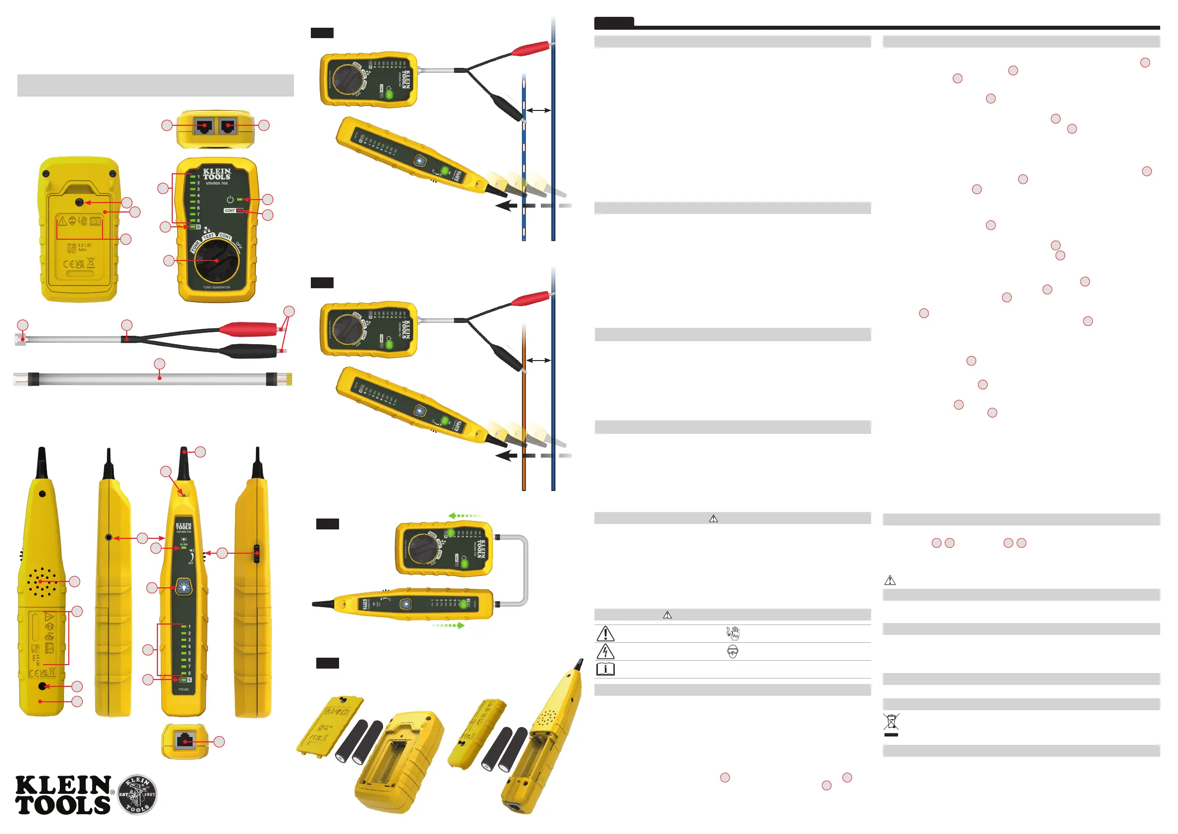
FEATURE DETAILS - TONER
T1
Power Indicator
T8
RJ45 Cable
T2
"CONT" (Continuity) Indicator
T9
RJ12-To-Alligator Clip Cable
T3
Wire Map / Pinout Indicators
T9a
RJ12 Plug
T4
Shield Indicator
T9b
Alligator Clips
T5
Function Selector Switch
T10
Battery Cover
T6
RJ12 Port
T11
Battery Cover Screw
T7
RJ45 Port
T12
Warning Symbols
FEATURE DETAILS - PROBE
P1
Non-Metallic Conductive Tip
P8
Headphone Jack
P2
Worklight
P9
RJ45 Port
P3
Power Indicator
P10
Battery Cover
P4
Power/Volume Control Dial
P11
Battery Cover Screw
P5
Worklight On/Off Button
P12
Warning Symbols
P6
Wire Map / Pinout Indicators
P13
Speaker
P7
Shield Indicator
GENERAL SPECIFICATIONS - TONER
The Klein Tools VDV500-705T Toner is a tone generator for wire identification, wire tracing and wire
pair identification. It features a tone with a strong power output for tracing wires.
•
Operating Altitude: 6562 ft. (2000 m) maximum
•
Relative Humidity: 10% – 90% non-condensing
•
Operating Temp: 14° to 140°F (-10° to 60°C)
•
Storage Temp: -4° to 122°F (-20° to 50°C)
•
Dimensions: 2.51" x 4.33" x 1.24" (64 x 110 x 31 mm)
•
Weight: 4.0 oz. (113g) including batteries
•
Battery Type: 2 x 1.5V AAA
•
Battery Life: Active: 60 hours Standby/Storage: 3 years
•
Auto-Power Off: After 60 minutes of inactivity
•
Tone Power: 8dBm
•
Continuity Indication: Less than 10kΩ
•
Voltage Protection: Test Mode: 60V Tone Mode:
1000 Hz – 2000 Hz
NOTE:
The maximum voltage across Alligator Clips of the Toner is 60 volts in Test mode, and 20
volts in Continuity mode. Connecting the Toner to live mains AC power may damage it and pose a
safety hazard for the user.
Specifications subject to change.
GENERAL SPECIFICATIONS - PROBE
The Klein Tools VDV500-705P Probe is a tone tracer, featuring an inductive probe, a speaker for an
audible output, a headphone jack for use in noisy environments, and a worklight for use in dark spaces.
•
Operating Altitude: 6562 ft. (2000 m) maximum
•
Relative Humidity: 10% – 90% non-condensing
•
Operating Temp: 14° to 140°F (-10° to 60°C)
•
Storage Temp: -4° to 140°F (-20° to 60°C)
•
Dimensions: 1.46" x 7.98" x 1.07" (37 x 203 x 27 mm)
•
Weight: 3.5 oz. (99 g) including batteries
•
Maximum Volume: 90 dB
•
Battery Type: 2 x 1.5V AAA Alkaline
•
Battery Life: Active: 18 hours Standby/Storage: 3 years
•
Auto-Power Off: After 10 minutes of inactivity
Specifications subject to change.
WARNINGS
To ensure safe operations and service of the instruments, follow these instructions. Failure to observe
these warnings can result in re, electric shock, severe injury or death.
•
The Toner and Probe are designed for use on cabling systems for testing when NOT energized.
•
DO NOT use instruments if they are wet, as it could pose a shock hazard.
•
DO NOT use instruments if they are damaged in any way.
•
Turn off instruments and disconnect Alligator Clips and RJ11/RJ45 connectors before
attempting to replace batteries.
•
The battery door must be in place and secure before you operate the instrument.
•
DO NOT open the case, other than the battery compartment.
WARNING SYMBOLS ON INSTRUMENTS
Warning or caution
Do not use on live electrical circuits
Warning – Risk of electric shockWear approved eye protection
Read instructions before using
OPERATING INSTRUCTIONS
READ ALL INSTRUCTIONS BEFORE OPERATING AND RETAIN INSTRUCTIONS FOR FUTURE REFERENCE.
This tone and probe test kit traces non-energized wires. The toner transmits on non-energized wires
using the 3rd and 4th contacts of the RJ12 terminal jack or the 4th and 5th contacts of the RJ45
terminal jack. Included with this kit are an RJ12-to-alligator clips test wire to use on unterminated
wires or coaxial cable, as well as an RJ45 terminated jumper. These are to be used as an interface
with the cable to be traced, if required. The probe is used to locate the toned wire at the far end of
the cable. See below for specific details.
CONTINUITY TEST
The Toner transmits frequencies on non-energized wires only. Connect the cable to be tested to the Toner,
or, if necessary, connect the Alligator Clip Cable
T9
to the Toner, then attach the Alligator Clips
T9b
to the
wires to be tested. If the resistance of the circuit is less than 10kΩ, the "CONT" Indicator
T2
will illuminate
red and no toning can occur. If there is continuity on the cables to be tested, toning cannot be performed.
OPERATING INSTRUCTIONS
TRACING PAIRED WIRES (FIG. 1)
1. Connect the cable to be tested to the Toner, or, if necessary, connect the Alligator Clip Cable
T9
to
the Toner, then attach the
red Alligator Clip
T9b
to one of the wires in the pair to be traced. Connect
the black Alligator Clip
T9b
to the other wire in the pair to be traced.
2. Perform Continuity Test as described previously to verify the wire path is open for toning.
3. Turn the Function Selector Switch
T5
to "TONE" to initiate toning
.
4. At the far end of the wire pair to be traced, spread the wires apart at least 2" (51 mm), if possible.
5. Turn on the Probe by rotating the Power/Volume Control Dial
P4
counterclockwise, to desired volume.
6. Use the Probe to scan the cable’s wire pairs. Move the Probe's tip
P1
slowly across the wires. The
Probe’s volume will increase as it approaches the toned pair. When the Probe’s volume is high over
the first wire, low in the middle (between) the two wires, and high over the second wire, you have
located the pair of wires you are tracing.
RJ45 TERMINATED DATA CABLE WIRE MAP TESTING (FIG. 3)
1. Insert one end of the data cable to be tested into the Toner's RJ45 port
T7
.
2. Insert opposite end of cable into the Probe's
RJ45 port
P9
.
3. Turn the Toner's
Function Selector Switch
T5
to "TEST".
4. A wire pin-to-pin map will be displayed on both the Toner and the Probe. The Toner's Wire Map Pinout
Indicators
T3
will slowly blink in order, 1 through 8, to indicate which pin on the Toner end of the cable
is being mapped. Simultaneously, The Probe's Wire Map Pinout Indicators
P6
will illuminate to indicate
which pin on the Probe end of the cable is connected to the actively indicated pinout on the Toner end
(for example, if pin 3 on the Toner end of the cable is connected to pin 6 on the Probe end of the cable,
when the Toner's #3 Pinout Indicator illuminates, the Probe's #6 Pinout Indicator will illuminate).
5. If the cable being mapped is terminated in T568A, T568B, or Straight-Through wiring, the Probe's
Wire Map Pinout Indicators
P6
will illuminate
1 through 8, in the order of contact pin termination,
in unison with the Toner's Indicators.
6. The test will be repeated until one (or both) end(s) of the cable is/are disconnected, or until the
Toner's
Function Selector Switch
T5
is rotated out of the "TEST" setting.
USING THE PROBE'S WORKLIGHT
The Probe has a worklight
P2
to aid in illuminating dark or low-light work areas. Press the Worklight
On/Off button for less than one second
P5
to turn the light on and off.
CUSTOMER SERVICE
KLEIN TOOLS, INC.
450 Bond Street Lincolnshire, IL 60069 1-800-553-4676
customerservice@kleintools.com www.kleintools.com
CLEANING
Be sure instrument is turned off and wipe with a clean, dry lint-free cloth.
Do not use
abrasive cleaners or solvents.
STORAGE
Remove the batteries when
instrument
is not in use for a prolonged period of time. Do not expose
to high temperatures or humidity. After a period of storage in extreme conditions exceeding the
limits mentioned in the GENERAL SPECIFICATIONS section, allow the equipment to return to normal
operating conditions before using.
WARRANTY
www.kleintools.com/warranty
DISPOSAL / RECYCLE
Do not place equipment and its accessories in the trash. Items must be properly disposed of in
accordance with local regulations. Please see www.epa.gov/recycle for additional information.
BATTERY REPLACEMENT (FIG. 4)
1. Turn off instrument(s) before attempting to replace batteries.
2. Loosen screw
T11
,
P11
on battery cover
T10
,
P10
.
3. Remove and properly dispose of two 1.5V AAA batteries.
4. Install new batteries (note proper polarity).
5. Replace battery cover and fasten securely with screw.
To avoid risk of electric shock, do not operate while battery door is removed.
TRACING NON-PAIRED WIRES (FIG. 2)
1. Connect the cable to be tested to the Toner, or, if necessary, connect the Alligator Clip Cable
T9
to
the Toner, then attach the
the red Alligator Clip
T9b
to the wires to be traced.
2. Connect the black Alligator Clip
T9b
to another wire in the cable, but preferably not in the same pair
(connect to ground, if available). When tracing a shielded cable, connect the red Alligator Clip to the outer
shield, and the black Alligator Clip to the center conductor or ground.
3. Perform Continuity Test as described previously to verify the wire path is open for toning.
4. Turn the Function Selector Switch
T5
to "TONE" to initiate toning
.
5. At the far end of the cable, spread the wires apart at least 2" (51 mm), if possible.
6. Turn on the Probe by rotating the Power/Volume Control Dial
P4
counterclockwise, to desired volume.
7. Use the Probe to scan the cable’s wires. Move the Probe's tip
P1
slowly across the wires. The
Probe’s volume will increase as it approaches the toned wire
APPLICATION HINTS
• When tracing wires terminated to a terminal block such as a “66 block”, attaching both generator leads
to the cable or pair tends to contain the signal within the cable pair. This causes cancellation of the
radiated signal. The tracer must nearly touch the end of the cable to detect the signal, which is helpful
when the wires are close together or when terminated.
• Connecting one generator lead to a wire is normally sufficient to trace the cable. The more wires in a
cable connected in parallel to the generator, the stronger the radiated signal.
• When necessary to maximize radiated signal, connect one lead of the generator to the wire or cable
and the other end to ground, such as electric box, metallic water pipe or ground rod.
• Connect the generator to the ungrounded shield of a coax cable for the strongest signal. If the generator
is connected to the center lead the shield will do its job and shield the signal from being radiated.
VDV500-705-1390324ART - Tone & Probe Test & Trace Kit.indd 1VDV500-705-1390324ART - Tone & Probe Test & Trace Kit.indd 17/30/21 9:49 AM7/30/21 9:49 AM
Specyfikacje produktu
| Marka: | Klein Tools |
| Kategoria: | Sprzęt pomiarowy |
| Model: | VDV770-855 |
Potrzebujesz pomocy?
Jeśli potrzebujesz pomocy z Klein Tools VDV770-855, zadaj pytanie poniżej, a inni użytkownicy Ci odpowiedzą
Instrukcje Sprzęt pomiarowy Klein Tools

14 Stycznia 2025
14 Stycznia 2025
1 Stycznia 2025
27 Grudnia 2024
9 Października 2024
9 Października 2024
9 Października 2024
6 Października 2024
6 Października 2024
5 Października 2024
Instrukcje Sprzęt pomiarowy
Najnowsze instrukcje dla Sprzęt pomiarowy
3 Kwietnia 2025
3 Kwietnia 2025
3 Kwietnia 2025
3 Kwietnia 2025
3 Kwietnia 2025
3 Kwietnia 2025
3 Kwietnia 2025
3 Kwietnia 2025
3 Kwietnia 2025
3 Kwietnia 2025