Instrukcja obsługi Noctua NH-L12SX77
Noctua Sprzęt komputerowy NH-L12SX77
Przeczytaj poniżej 📖 instrukcję obsługi w języku polskim dla Noctua NH-L12SX77 (2 stron) w kategorii Sprzęt komputerowy. Ta instrukcja była pomocna dla 29 osób i została oceniona przez 2 użytkowników na średnio 4.0 gwiazdek
Strona 1/2
Scan this code to
display multilingual
manuals on your
phone.
NOCTUA NH-L12Sx77
INSTALLATION MANUAL
This manual will guide you through the installation process
of the SecuFirm2™ mounting system step by step.
Prior to installing the cooler, please consult the compatibility
centre on our website (ncc.noctua.at) and verify that the
cooler is fully compatible with your motherboard, CPU,
RAM and case. Please also make sure that there are no
compatibility issues with any other components.
Double check that the heatsink and fan clips do not make
contact with the VGA card, other PCIe cards, motherboard
heatsinks or any other components.
Noctua cannot be held responsible for any damage or
losses caused by compatibility issues.
Should you encounter any difficulties, please check the
FAQs on our website () and don’t hesitate to faqs.noctua.at
contact our support team at support@noctua.at.
Multilingual versions of this manual are available on our
website: www.noctua.at/manuals
Dear customer,
Thank you very much for choosing the Noctua NH-L12Sx77.
The NH-L12Sx77 is a slightly taller variant of the award-
winning NH-L12S, offering improved cooling performance
as well as enhanced motherboard and RAM compatibility.
Enjoy your Noctua NH-L12Sx77!
Yours sincerely,
Roland Mossig, Noctua CEO
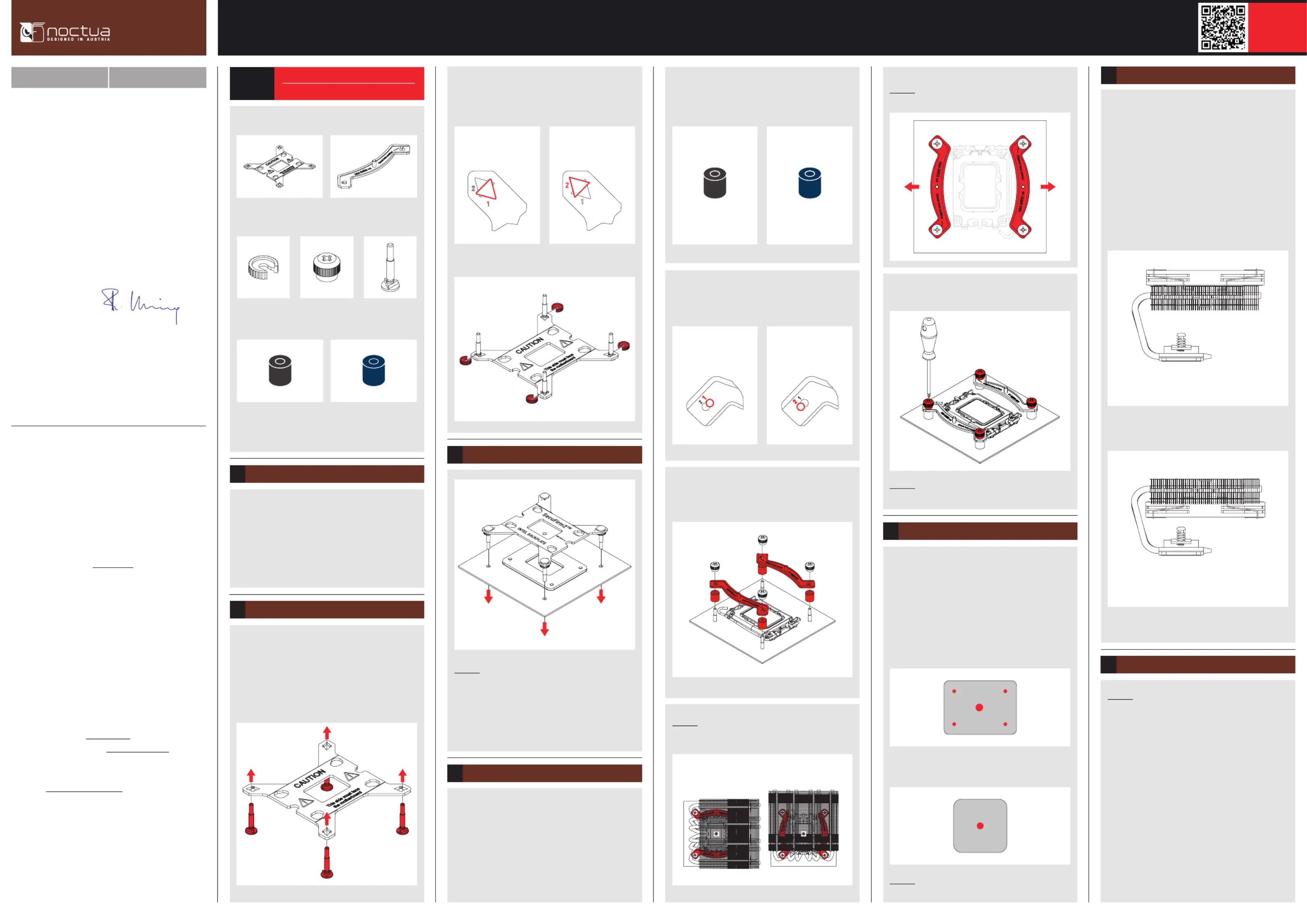
Fan configuration6
The NH-L12Sx77 ships with the fan installed underneath
the fins (low-profile mode).
Alternatively, you can take off the fan and install it on
top of the fins to make more room for tall RAM or other
components (high-clearance mode).
Note that the NH-L12Sx77 will provide best performance to
noise efficiency in high-clearance mode.
High-clearance mode
Low-profile mode
INTELAMD
Fastening the heatsink to the CPU7
Caution: Please first take off the protection cover at the
bottom side of the heatsink.
Then put the heatsink onto the CPU and screw it to the
screw threads of the mounting bars.
Perform 2-3 turns on each screw, then repeat until both are
fully tightened.
Note that you can reach through the blades of the fan using
the supplied screwdriver. There is thus no need to take off
the fan for installation.
Required mounting parts:
If you would like to use the cooler on an assembled
system and your case does not have a cut-out at
the rear side of the motherboard tray, you must first
remove the motherboard from the case in order to be able
to install the supplied backplate.
Removing the motherboard
1
Setting up the backplate
2
First, identify the side of the backplate that should face the
motherboard (marked with caution signs). Then choose the
appropriate hole spacing for your socket and insert the four
bolts into the backplate from the opposite side (marked
with model name, SecuFirm2™ branding and numbers for
hole spacing) at the appropriate position.
4x NM-IPS1
black plastic spacers for
LGA1200/115x
4x NM-IPS3
blue plastic spacers for
LGA1851/1700
Put the plastic spacers onto the bolts of the backplate, then
add the mounting bars.
Caution: Choose the alignment of the mounting bars
according to the desired final orientation of the cooler.
Caution: Make sure that the curved sides of the mounting
bars are pointing outwards.
Fix the mounting bars using the four NM-STS1 thumb
screws.
Caution: Gently tighten the screws until they stop, but do
not use excessive force (max. torque 0.6 Nm).
Applying the thermal paste5
If there are residual traces of thermal paste or thermal pads
on your CPU, please clean them off first. Then apply the
supplied NT-H2 thermal paste onto the CPU as shown in
the following images.
For LGA1851/LGA1700, apply 5 small dots; 4 dots with
~2mm diameter near the corners plus 1 dot with 3-4mm
diameter in the centre:
Caution: Applying too much thermal paste will lower heat
conductivity and cooling performance!
Use hole position 1 for LGA1200/LGA115x (LGA1150,
LGA1151, LGA1155, LGA1156) and hole position 2 for
LGA1851/LGA1700:
4x NM-IBT5
bolts
4x NM-ICS1
clip-on spacers
4x NM-STS1
thumb screws
2x NM-IMB3
mounting bars
1x NM-IBP4
backplate
NM-IPS3 (blue)
LGA1851/1700
NM-IPS1 (black)
LGA1200/115x
LGA1851, LGA1700,
LGA1200 & LGA115x
Use the black NM-IPS1 plastic spacers for LGA1200/
LGA115x (LGA1150, LGA1151, LGA1155, LGA1156) and
the blue NM-IPS3 spacers for LGA1851/LGA1700.
For LGA1200/LGA115x (LGA1150, LGA1151, LGA1155,
LGA1156) apply a single 4-5mm dot in the centre:
Position 1:
LGA1200/115x
Position 2:
LGA1851/1700
Fix the bolts using the NM-ICS1 clip-on spacers.
Attaching the backplate3
Caution: The supplied backplate will install over the
motherboard’s stock backplate, so the motherboard’s stock
backplate must not be taken off.
Place the backplate on the rear side of the motherboard so
that the bolts protrude through the mounting holes.
Please first choose the correct set of plastic spacers and
the correct set of holes on the mounting bars according
to whether you are using an LGA1200/LGA115x (LGA1150,
LGA1151, LGA1155, LGA1156) or an LGA1851/LGA1700
socket motherboard.
Installing the mounting bars4
Position 1:
LGA1200/115x
Position 2:
LGA1851/1700
Use hole position 1 for LGA1200/LGA115x (LGA1150,
LGA1151, LGA1155, LGA1156) and hole position 2 for
LGA1851/LGA1700:
INTEL INTEL
Orientation 1
(default orientation)
Orientation 2
Specyfikacje produktu
| Marka: | Noctua |
| Kategoria: | Sprzęt komputerowy |
| Model: | NH-L12SX77 |
Potrzebujesz pomocy?
Jeśli potrzebujesz pomocy z Noctua NH-L12SX77, zadaj pytanie poniżej, a inni użytkownicy Ci odpowiedzą
Instrukcje Sprzęt komputerowy Noctua

9 Kwietnia 2025
9 Stycznia 2025
9 Stycznia 2025
9 Października 2024
9 Października 2024
9 Października 2024
9 Października 2024
9 Października 2024
3 Października 2024
3 Października 2024
Instrukcje Sprzęt komputerowy
Najnowsze instrukcje dla Sprzęt komputerowy
9 Kwietnia 2025
9 Kwietnia 2025
8 Kwietnia 2025
8 Kwietnia 2025
8 Kwietnia 2025
8 Kwietnia 2025
8 Kwietnia 2025
8 Kwietnia 2025
8 Kwietnia 2025
8 Kwietnia 2025