Instrukcja obsługi Optex OA-6500
Optex Czujnik Deur/ramki OA-6500
Przeczytaj poniżej 📖 instrukcję obsługi w języku polskim dla Optex OA-6500 (2 stron) w kategorii Czujnik Deur/ramki. Ta instrukcja była pomocna dla 48 osób i została oceniona przez 3 użytkowników na średnio 4.7 gwiazdek
Strona 1/2
OA-6500S T
ENGLISH
5925242 JUN 2017
Specifications
: OA-6500S T
: Black
: 8'2" (2.5m) to 21'4" (6.5m)
: See Detection area
: Active infrared reflection method
(All presence detection)
: 1st and 2nd rows: -15° to +5°
3rd row: +30° to +50°
: 12 to 24VAC ±10% (50 / 60Hz)
12 to 30VDC ±10%
: < 2.5W (< 3.5VA at AC)
: Green / Stand-by
Red / 1st row detection
Orange / 2nd and 3rd rows detection
Model
Color
Mounting height
Detection area
Detection method
Depth adjustment
Power supply
Power consumption
Operation indicator
: 3rd row detection
N.C. / N.O. selectable
50V 0.3A MAX.(Resistance load)
: Opto coupler
Voltage 5 to 30VDC
Current 6mA Max. (30VDC)
: 1st or 2nd row detection
N.C. / N.O. selectable
50V 0.3A MAX.(Resistance load)
: Approx. 0.5sec.
: < 0.3sec.
: -4°F to 131°F(-20°C to +55°C)
: < 80%
: IP44
: 21.2 oz (600g)
: 1 Cable 25' (7.62m)
2 Mounting screws
1 Mounting template
1 Operation manual
1 High mount window
1 Protection sticker
Activation output
Test input
Safety output
Output hold time
Response time
Operation temperature
Operating humidity
IP rate
Weight
Accessories
The specifications herein are subject to change
without prior notice due to improvements.
NOTE
NOTE
1
3
2
WARNING
Danger of electric shock.
Do not use the sensor without the cover.
When using the cable knockout, install the sensor indoors or use the rain-cover
(Separately available) otherwise electric shock or breakdown of the sensor may
occur.
4
Wire the cable to the door controller as shown below.
1.Plug the connector of the sensor.
2.Supply power to the sensor. Adjust the detection area and set the dipswitches. (See ) Adjustments
1.Put the protection sticker as shown below.
Before starting the procedure, make sure that the power is turned OFF.
When passing the cable through the hole, do not tear the shield.
otherwise it may cause electric shock or breakdown of the sensor.
WARNING
Danger of electric shock.
NOTE
Installation
Grey
Grey
White
Yellow
Knockout
1'1 5/16" (338)
5/8"(16)
1 7/16"
(36.5)
1/8" (3)
Mounting holes ø1/8" (ø3.4mm)
Wiring hole ø5/16" (ø8.0mm)
The lower edge
of the header
Make sure to connect the cable correctly to the door controller before turning the power ON.
When turning the power ON or after adjusting the settings, do not enter the detection area for more
than 10 seconds in order to enable the presence detection.
When changing the settings of dipswitch, see .Adjustments 3 Dipswitch settings
See for settings.Adjustments 3-1
12 to 24VAC (50 / 60Hz)
12 to 30VDC
[inch(mm)]
1
Adjustments
Detection window selection
ON
12567834
ON
12567834
ON
12567834
ON
12567834
ON
12567834
ON
12567834
According to the mouting height, select proper detection window.
8'2"(2.5m) to 16'5"(5.0m) : Standard window(default)
16'5"(5.0m) to 21'4"(6.5m) : High mount window
window
1. Remove the screws
2.Take the windows off.
3.Attach the windows.
4.Fix the windows with the screws.
Drill two mounting holes ø1/8" (ø3.4mm) on the header.
To pass the cable through the header, drill a wiring hole of ø5/16" (ø8mm).
Detection area
: Emitting spots
: Emitting spots (Can be eliminated)
The actual detection area may become smaller
depending on the ambient light, the color / material of
the object or the floor as well as the entry speed of
the object.
The sensor may not be activated when the entering
speed of the object or a person is slower than
50mm / sec. or faster than 1500mm / sec.
NOTE
A
B
C
D
E
F
G
Z
8'2"
(2,500)
11'6"
(3,500)
14'9"
(4,500)
18'1"
(5,500)
21'4"
(6,500)
6"
(150)
8"
(210)
11"
(280)
1'1"
(340)
1'4"
(400)
6"
(150)
9"
(220)
11"
(280)
1'1"
(340)
1'4"
(410)
1'10"
(560)
2'7"
(790)
3'4"
(1010)
4'1"
(1240)
4'10"
(1470)
2'3"
(680)
3'2"
(960)
4'1"
(1240)
4'11"
(1510)
5'11"
(1790)
4'5"
(1340)
6'2"
(1870)
7'11"
(2410)
9'8"
(2940)
11'5"
(3480)
5'1"
(1530)
7'1"
(2150)
9'1"
(2760)
9'2"
(2790)
10'10"
(3300)
11'11"
(3640)
16'9"
(5100)
21'7"
(6560)
23'9"
(7230)
28'1"
(8550)
12'7"
(3840)
17'8"
(5380)
22'8"
(6910)
25'
(7620)
29'7"
(9010)
[feet,inch(mm)]
Mounting
height
WindowStandard window
High mount window
Values of the chart are based on the following depth
angle adjustment settings;
[Standard window]
: Emitting spots
: Emitting spots (Can be eliminated)
2nd row
1st row
3rd row
Z
A
B
C
D
F
G
E
[High mount window]
2nd row
1st row
3rd row
Z
A
B
C
D
F
G
E
Mounting
height
Mounting
height
Manufacturer's statement
WARNING
CAUTION
NOTE
WARNING
Do not wash, disassemble, rebuild or repair the sensor, otherwise
it may cause electric shock or breakdown of the equipment.
Danger of electric shock.
Special attention is required to the section of this symbol.
NOTE
Read this operation manual carefully before use to ensure proper operation of this product.
Failure to read this operation manual may cause improper operation and may result in serious injury or death of a person.
The meanings of the symbols are as follows.
The following conditions are not suitable for sensor installation.
- Fog or exhaust emission around the door.
- Wet floor.
- Vibrating header or mounting surface.
- Moving objects or objects that emit light near the detection area.
- Highly reflecting floor or highly reflecting objects around the door.
NOTE
1. This product is a non-contact switch intended for header mount for use on industrial door.
Do not use for any other applications.
2. When setting the sensor's detection area, make sure that there is no traffic around the installation site.
3. Before turning the power ON, check the wiring to prevent damage or malfunction of equipment connected
to the product.
4. Only use the product as specified in the operation manual provided.
5. Be sure to install and adjust the sensor in accordance with the local laws and standards of the country in
which the product is installed.
6. Before leaving the installation site make sure that the product is operating properly and instruct the building
owner/operator on proper operation of the door and the product.
7.The product settings can only be changed by an installer or service engineer. When changed, the
changed settings and the date shall be registered in the maintenance logbook accompanying the door.
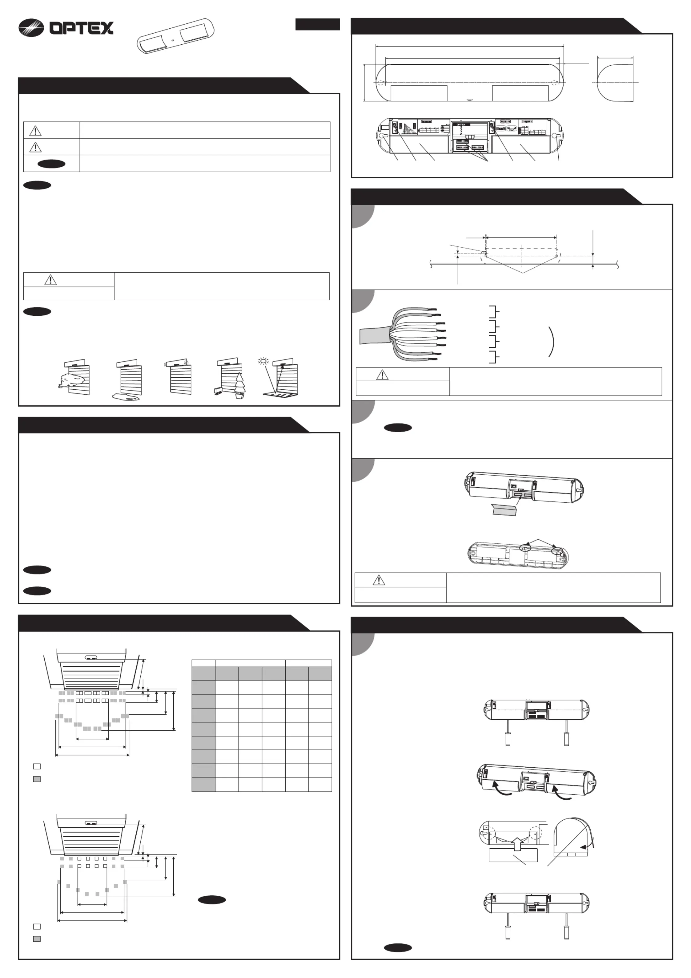
Outer dimensions and part names
2 7/8"(73)
1'2 5/8"(371)
2 13/16"(72)
3/8"(10)
1'1 5/16"(338)
(1) 1st and 2nd rows adjustment screw
(2) 3rd row adjustment screw
(3) Detection window
(4) Mounting holes
(5) Dipswitches
[inch(mm)]
+50°
+30°
+40°
SW2SW3
SW1
ON
12567834
ON
12567834
ON
12567834
+5
°
-15
°
-5
°
(1)
(2)
(3)
(3)
(4)
(4)
(5)
Simultaneous output
3
2
Safety output
1
Activation output
N.O.
N.C.
2nd row output
4
5,6,7
Activation
Safety
Setting 3
Setting 4
Setting 1
Setting 2
Frequency
Make sure that Dipswitch 5 is set to “OFF” for any setting.
N.O.
N.C.
ON
OFF
8
Low
High
Depth adjustment
1st and 2nd rows3rd row
SW1
Test input
Power supply :12 to 24VAC±10% / 12 to 30VDC±10%
Power consumption : < 2.5W ( < 3.5VA at AC)
Activation output (When 3rd row detects.)
N.C. / N.O. selectable , 50V0.3A MAX.(Resistance load)
Safety output (When 1st or 2nd row detects.)
N.C. / N.O. selectable , 50V0.3A MAX.(Resistance load)
Test input
Opto coupler, Voltage : 5 to 30VDC, Max.
Grey
Grey
White
Yellow
White stripe
Yellow stripe
Red +
Black -
Wiring
OA-6500S T
On delay
2 sec.
Door cancel
Automatic infinite
presence detection
Sensitivity
Presence
timer
1,2
10min.
2sec.
60sec.
7,8
High
Low
Middle
S-High
3
Presence area
1st & 2nd
1st to 3rd
4
ON
OFF
5
ON
OFF
ON
OFF
ON : Active
OFF : Eliminate
6
SW3
Detection area pattern
1st and 2nd rows3rd row
Detection area 2 (3) can not be eliminated
when dipswitch 1 (4) is not eliminated.
SW2
12
34
5
8
67
1st and 2nd rows
3rd row
: +5°
: +30°
White stripe
Yellow stripe
Red (+)
Black (-)
Safety output
Power supply
Activation output
Test input
2.Place the housing cover.
If wiring is to be exposed, break the knockout.
When changing window follow procedure below.
NOTE
Please carry out operation check after changing window.
Failure to follow the instructions provided with this indication and improper handling may cause
death or serious injury.
Failure to follow the instructions provided with this indication and improper handling may cause
injury and/or property damage.
LED will be turned off about 500ms when the
sensor Test output signal works well.
Specyfikacje produktu
| Marka: | Optex |
| Kategoria: | Czujnik Deur/ramki |
| Model: | OA-6500 |
Potrzebujesz pomocy?
Jeśli potrzebujesz pomocy z Optex OA-6500, zadaj pytanie poniżej, a inni użytkownicy Ci odpowiedzą
Instrukcje Czujnik Deur/ramki Optex

30 Grudnia 2025
6 Grudnia 2024
6 Grudnia 2024
6 Grudnia 2024
5 Października 2024
4 Października 2024
23 Września 2024
17 Września 2024
5 Września 2024
29 Sierpnia 2024
Instrukcje Czujnik Deur/ramki
Najnowsze instrukcje dla Czujnik Deur/ramki
20 Grudnia 2024
14 Października 2024
9 Października 2024
9 Października 2024
9 Października 2024
8 Października 2024
8 Października 2024
7 Października 2024
7 Października 2024
7 Października 2024