Instrukcja obsługi Panasonic WV-SFR531
Panasonic kamera bezpieczeństwa WV-SFR531
Przeczytaj poniżej 📖 instrukcję obsługi w języku polskim dla Panasonic WV-SFR531 (4 stron) w kategorii kamera bezpieczeństwa. Ta instrukcja była pomocna dla 43 osób i została oceniona przez 7 użytkowników na średnio 4.5 gwiazdek
Strona 1/4
WV-SFN531
WV-SFN531
(This illustration represents WV-SFN531.)
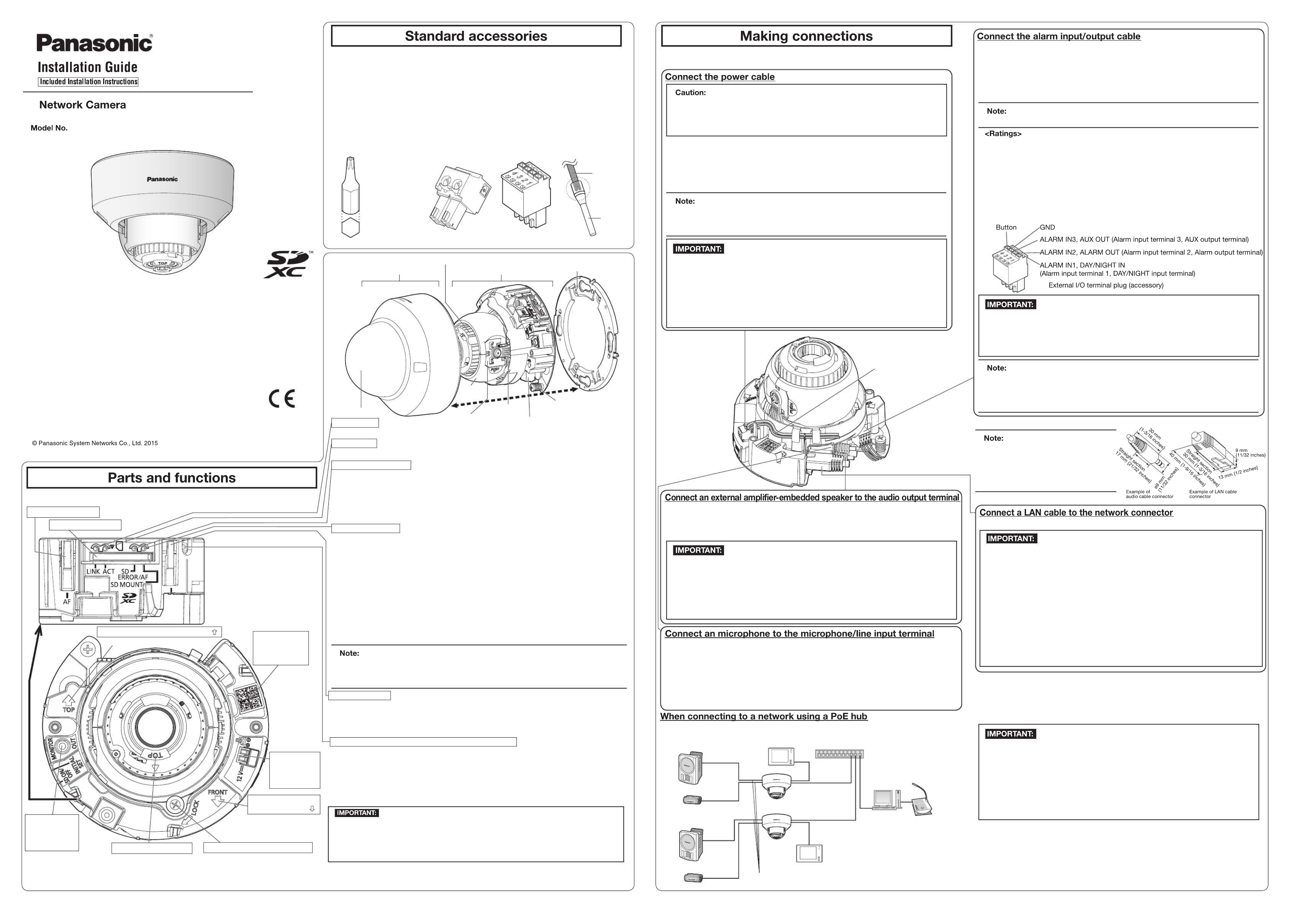
●This manual describes the installation procedures, network camera installation, cable connections,
and the angle of view adjustment.
●Before reading this manual, be sure to read the Important Information.
●This manual describes how to install the network camera using model WV-SFN531 as an example.
PGQX1909ZA es0615-0 Printed in China
Important Information ...............................1 pc.
Installation Guide (this document) ............1 set
Warranty card ...........................................1 set
CD-ROM*1................................................1 pc.
Code label*2..............................................1 pc.
*1 The CD-ROM contains the operating instructions and different kinds of tool software programs.
*2 This label may be required for network management. The network administrator shall retain the
code label.
The following parts are used during installation procedures.
ⒶAttachment plate ..................................1 pc.
ⒷBit (Hex wrench, screw
size 6.35 mm {1/4 inches} T10) ...............1 pc.
Ⓒ
Template A (for the attachment plate)
......1 sheet
Ⓓ Power cord plug*3................................1 pc.
Ⓔ External I/O terminal plug*3..................1 pc.
Ⓕ MONITOR OUT conversion plug .........1 pc.
ⒼAuxiliary handle ...................................1 pc.
Azimuth adjustment ring
The component names of the camera are as follows. Refer to the illustration when installing or
adjusting the camera.
*2 Depending on the scanning application used, the Data Matrix may not be able to be read
correctly. In this case, access the site by directly entering the following URL.
http://security.panasonic.com/pss/security/support/qr_sp_select.html
Turn off each system’s power supply before making a connection. Before making connections,
prepare the required peripheral devices and cables.
Connect the output cable to the power cord plug (accessory).Ⓓ
Before starting the installation, check the entire system configuration. The following illustration
gives a wiring example of how to connect the camera to the network via a PoE device (hub).
<Required cable>
LAN cable (category 5e or better, straight)
Use a LAN cable (category 5e or better, cross) when directly connecting the camera to a PC.
*1 Recommended cable length from the speaker : less than 10 m {32.8 feet}
Recommended cable length from the microphone : less than 1 m {3.28 feet}
●Since the connector storage section
does not have a sufficient space, use
audio cables and a LAN cable that do
not exceed the sizes described in the
illustrations.
●Off, input, and output of the external I/O terminal 2 and 3 can be switched by con-
figuring the setting. Refer to the operating instructions on the provided CD-ROM for
further information about the EXT I/O terminal 2 and 3 (ALARM IN2, 3) settings
(“Off”, “Alarm input”, “Alarm output” or “AUX output”).
●Connect/disconnect the audio cables and turn on the power of the camera after turning
off the power of the audio output devices. Otherwise, loud noise may be heard from
the speaker.
●Make sure that the stereo mini plug is connected to this cable. When a monaural mini
plug is connected, audio may not be heard.
When connecting a monaural speaker with amplifier, use a locally procured conversion
cable (mono-stereo).
Connect a stereo mini plug (ø3.5 mm).
●Output impedance : Approx. 600 Ω (unbalanced)
●Recommended cable length : Less than 10 m {32.8 feet}
●Output level : –20 dBV
Connect a stereo mini plug (ø3.5 mm).
●Input impedance: Approx. 2 kΩ (unbalanced)
●Recommended cable length: Less than 1 m {3.28 feet} (for microphone input)
Less than 10 m {32.8 feet} (for line input)
●Recommended microphone: Plug-in power type (option)
● Supply voltage: 2.5 V ±0.5 V
● Recommended sensitivity of microphone: –48 dB ±3 dB (0 dB=1 V/Pa,1 kHz)
●Input level for the line input: Approx. –10 dBV
●Use all 4 pairs (8 pins) of the LAN cable.
●The maximum cable length is 100 m {328 feet}.
●Make sure that the PoE device in use is compliant with IEEE802.3af standard.
●When connecting both the 12 V DC power supply and the PoE device for power
supply, 12 V DC will be used for power supply.*
* If a 12 V DC power supply and a PoE hub or router are used at the same time,
network connections may not be possible. In this case, disable the PoE settings.
Refer to the operating instructions of the PoE hub or router in use.
* In the situation where a 12 V DC power supply and a PoE hub or router are used at
the same time and the 12 V DC power supply is then disconnected, the power
supply is stopped and the camera will restart.
●When the LAN cable is disconnected once, reconnect the cable after around
2 seconds. When the cable is quickly reconnected, the power may not be supplied
from the PoE device.
●Do not connect 2 wires or more directly to a terminal. When it is necessary to connect
2 or more wires, use a splitter.
●Install external devices so that they do not exceed the rating of the network camera.
●When using the EXT I/O terminals as the output terminals, ensure they do not
cause signal collision with external signals.
●The adjustment monitor is used for checking the adjustment of the angular field of
view when installing the camera or when servicing. It is not provided for recording/
monitoring use.
●Depending on the monitor, some characters (camera title, preset ID, etc.) may not
be displayed on the screen.
●Use a switching hub or a router which is compliant with 10BASE-T/100BASE-TX.
●If a PoE hub is not used, each network camera must be connected to a 12 V DC
power supply.
●When using 12 V DC, power supply from a PoE hub or router is not required.
* Use a LAN cable (category 5e or better, 8 pins, straight).
Connect the cables of external devices to the External I/O terminal plug (accessory).Ⓔ
q When connecting an external device, strip 8 mm - 9 mm {5/16 inches - 11/32 inches} of the
outer jacket of the cable and twist the cable core to prevent the short circuit first.
Specification of cable (wire): AWG20 - AWG26, Single core, twisted
w Push down the button of the desired terminal on the external I/O terminal plug with a ball-
point pen, and release the button when the cable of the external device is fully inserted
into the terminal hole.
●Check whether the stripped part of the wire is not exposed and is securely connected.
●ALARM IN1(DAY/NIGHT IN), ALARM IN2, ALARM IN3
Input specication : No-voltage make contact input (4 V - 5 V DC, internally pulled up)
OFF : Open or 4 V - 5 V DC
ON : Make contact with GND (required drive current: 1 mA or more)
●ALARM OUT, AUX OUT
Output specication
: Open collector output (maximum applied voltage: 20 V DC)
Open : 4 V - 5 V DC by internal pull-up
Close : Output voltage 1 V DC or less (maximum drive current: 50 mA)
* The default of EXT I/O terminals is “Off”.
●The 12 V DC power supply shall be insulated from the commercial AC power.
●Be sure to use the power cord plug (accessory) provided with this product.Ⓓ
●Be sure to fully insert the power cord plug (accessory) into the 12 V DC power Ⓓ
supply terminal. Otherwise, it may damage the camera or cause malfunction.
●When installing the camera, make sure that excessive force is not applied to the
power cable.
●
Be sure to use an AC adaptor compliant with the Specifications (written in the indication
label on the bottom side of this unit) regarding power source and power consumption.
●A READILY ACCESSIBLE DISCONNECT DEVICE SHALL BE INCORPORATED
TO THE EQUIPMENT POWERED BY 12 V DC POWER SUPPLY.
●ONLY CONNECT 12 V DC CLASS 2 POWER SUPPLY (UL 1310/CSA 223) or
LIMITED POWER SOURCE (IEC/EN/UL/CSA 60950-1).
q Loosen the screw of the power cord plug (accessory), strip 3 mm to 7 mm {1/8 inches to
9/32 inches} from the end of the wire, twist the stripped part of the wire sufficiently to avoid
short circuit, and then connect the output cable to the power cord plug (accessory).
w Tighten the screw of the power cord plug. (Recommended tightening torque: 0.34 N·m
{0.25 lbf·ft})
●Check whether the stripped part of the wire is not exposed and is securely connected.
●
When connecting an external power supply to the camera, use the AWG16 to AWG24
single-wired or stranded wired cables.
ⒹⒺ
4321
Ⓑ
(Hex wrench, screw
size 6.35 mm
{1/4 inches} T10)
For U.S. and Canada:
Panasonic System Communications
Company of North America,
Unit of Panasonic Corporation
of North America
www.panasonic.com/business/
For customer support, call 1.800.528.6747
Two Riverfront Plaza, Newark, NJ 07102-5490
Panasonic Canada Inc.
5770 Ambler Drive, Mississauga,
Ontario, L4W 2T3 Canada
(905)624-5010
www.panasonic.ca
For Europe and other countries:
Panasonic Corporation
http://www.panasonic.com
Panasonic System Networks Co., Ltd.
Fukuoka, Japan
Authorised Representative in EU:
Panasonic Testing Centre
Panasonic Marketing Europe GmbH
Winsbergring 15, 22525 Hamburg, Germany
*3 The external I/O terminal plug and power cord plug are attached to the camera.
4321
Ⓔ
●When the INITIAL SET button (i.e. the initializing button) is pressed (less than 1 second) to
switch the output signal of the MONITOR OUT terminal (NTSCPAL output), the MONITOR
OUT terminal can be switched for the NTSC monitor/PAL monitor.
●
When the camera is initialized, the settings including the network settings will be initialized.
Note that the CRT key (SSL encryption key) used for the HTTPS protocol will not be initialized.
● Before initializing the settings, it is recommended to write down the settings in advance.
● Do not turn off the power of the camera during the process of initialization. Otherwise, it
may fail to initialize and may cause malfunction.
●How to initialize the camera
Follow the steps below to initialize the network camera.
q
Turn off the power of the camera. When using a PoE hub, disconnect the LAN cable from the camera.
When using an external power supply, disconnect the power cable connector of the camera.
w
Turn on the power of the camera while holding down the INITIAL SET button, and keep the INITIAL SET button
held down till the SD MOUNT indicator is lit in green (more than 10 seconds). In about 2 minutes after releasing
the INITIAL SET button, the camera will start up and the settings including the network settings will be initialized.
INITIAL SET button (Initializing / NTSCPAL switch button)
●When an SD memory card is inserted and could Lights off → Blinks green →
be recognized Lights off
●When data can be saved after the SD memory card is Lights off → Lights green
inserted and the SD ON/OFF button is pressed
(less than 1 second)
●When data can be saved to the SD memory card Lights green
●When the SD memory card is removed after holding
Lights green → Blinks green →
down the SD ON/OFF button (about 2 seconds)
Lights off (recording)
Lights green → Lights off
(waiting for recording)
●
When data cannot be saved to the SD memory card because
Lights off
an abnormality was detected or the SD memory card is
configured not to be used
●Lighting/blinking LED can be turned off with the software settings at any time. (The initial
state is lighting or blinking.) Set the LED to be solid off if necessary, depending on the
installation conditions. (☞ Operating instructions included in the CD-ROM)
SD MOUNT indicator
q When the SD ON/OFF button is pressed (less than 1 second), the SD MOUNT indicator lights
up in green and data can be saved to the SD memory card*1.
w When the SD ON/OFF button is held down (about 2 seconds), the SD MOUNT indicator lights
off and the SD memory card can be removed.
SD ON/OFF button
●
When the camera is able to communicate with the connected device
Lights orange
LINK indicator
●When data is being sent via the network camera Blinks green (accessing)
ACT indicator
Powered speakerAdjustment monitorPoE device (hub)
LAN cable
(category 5e or better, straight)
PC
LAN cable (category
5e or better, straight)
LAN cable
(category 5e or better, straight)
Adjustment monitor
Recommended total extended
cable length*1
Microphone
Powered speaker
Microphone
● When AF (Auto Focus) operation is being executed Blinks red (1 time/second)
●When the set is being started Lights red
●When an SD memory card is recognized normally Lights red → Lights off
●When an abnormality is detected in the SD memory card Lights red → Stays red
or the SD memory card slot is not used after
the camera has started.
SD ERROR/AF indicator
WV-SFR531/WV-SFN531
WV-SFN531
*1 SDXC/SDHC/SD memory card
is described as SD memory
card.
Pan table fixing screw with washer
Auto focus (AF) button
● FRONT must positioned in
front of the camera (on the
Panasonic logo side).
MONITOR OUT
terminal (factory
shipment: NTSC
monitor)
Direction marker for installation (TOP)Two-dimensional
barcode (Data
Matrix): To our
website*2
Screen display top (TOP)
SD memory card*1 slot
Direction marker for
installation (FRONT)
● Points up when installing to a wall.
Ⓓ Power cord
plug (accessory)
12 V DC power
supply terminal
Panning table
Enclosure Camera
ⒶAttachment plate
(accessory)
Ⓔ External I/O terminal plug (accessory)
Inner
cover
Dome cover
Camera xing screw
Tilting table
Ⓖ
Zoom knob
Auxiliary
handle
* Route the power cable as
shown in the following
illustration, and do not clip
the power cable when
mounting the enclosure.
● As necessary, use a
cable tie (locally
procured) to tie the
cables together.
Specyfikacje produktu
| Marka: | Panasonic |
| Kategoria: | kamera bezpieczeństwa |
| Model: | WV-SFR531 |
| Kolor produktu: | Biały |
| Rodzaj zasilania: | PoE |
| Wysokość produktu: | 102.5 mm |
| Szerokość produktu: | 129.5 mm |
| Głębokość produktu: | 129.5 mm |
| Waga produktu: | 700 g |
| Technologia łączności: | Przewodowa |
| Liczba kamer: | 1 |
| Formaty kompresji: | H.264 |
| Obsługiwane systemy operacyjne Windows: | Tak |
| Obsługiwane typy kart pamięci: | SD, SDHC, SDXC |
| Przeznaczenie: | Wewnętrz i na wolnym powietrzu |
| Obsługa PoE: | Tak |
| Zakres temperatur (eksploatacja): | -10 - 50 °C |
| Zakres wilgotności względnej: | 10 - 90 % |
| Układ: | Douszne |
| Automatyczne ustawienie ostrości: | Tak |
| Możliwość przybliżenia: | Tak |
| Tryb nocny: | Tak |
| Obsługiwane formaty audio: | LC-AAC |
| Obsługiwane formaty plików wideo: | H.264 |
| Przewodowa sieć LAN: | Tak |
| Zintegrowany czytnik kart: | Tak |
| Model: | Kamera bezpieczeństwa IP |
| Technologia okablowania: | 10/100Base-T(X) |
| Maks. rozdzielczość: | 2048 x 1536 px |
| Typ mocowania: | Sufit |
| Długość ogniskowa: | 2.8 - 9.5 mm |
| Kodeki glosu: | G.711, G.726 |
| Cyfrowe zbliżenie: | 4 x |
| Obsługiwane rozdzielczości grafiki: | 160 x 120,160 x 90,320 x 180,320 x 240,400 x 300,640 x 360,640 x 480 (VGA),800 x 600 (SVGA),1280 x 720 (HD 720),1280 x 960,1600 x 1200 (UXGA),1920 x 1080 (HD 1080) |
| Redukcja hałasu: | Tak |
| Obsługa języków: | CHI (SIMPL), CHI (TR), DEU, ENG, ESP, FRE, ITA, JPN, POR, RUS |
| Typ przetwornika obrazu: | MOS |
| Balans bieli: | ATW, AWC |
| Standardowy zakres ogniskowania: | 0.3 - ∞ m |
| Min. Oświetlenie: | 0.0007 lx |
| Pełny HD: | Tak |
| Średnica: | 129.5 mm |
| Wbudowany HDD: | Nie |
| Wielkość czujnika CCD: | 1/3 " |
| Skanowanie progresywne: | Tak |
| Ilość klatek: | 60 fps |
| Liczba użytkowników: | 14 użyt. |
| Cechy zabiezpieczeń: | Odporny na wstrząsy |
| Efektywna rozdzielczość aparatu: | 2400000 px |
| Liczba języków: | 9 |
Potrzebujesz pomocy?
Jeśli potrzebujesz pomocy z Panasonic WV-SFR531, zadaj pytanie poniżej, a inni użytkownicy Ci odpowiedzą
Instrukcje kamera bezpieczeństwa Panasonic

31 Sierpnia 2024
30 Sierpnia 2024
30 Sierpnia 2024
7 Czerwca 2024
7 Czerwca 2024
7 Czerwca 2024
7 Czerwca 2024
7 Czerwca 2024
7 Czerwca 2024
7 Czerwca 2024
Instrukcje kamera bezpieczeństwa
Najnowsze instrukcje dla kamera bezpieczeństwa
9 Kwietnia 2025
5 Kwietnia 2025
5 Kwietnia 2025
5 Kwietnia 2025
2 Kwietnia 2025
2 Kwietnia 2025
30 Marca 2025
30 Marca 2025
30 Marca 2025
30 Marca 2025