Instrukcja obsługi Summit OTR24
Summit Magnetostrykcja OTR24
Przeczytaj poniżej 📖 instrukcję obsługi w języku polskim dla Summit OTR24 (3 stron) w kategorii Magnetostrykcja. Ta instrukcja była pomocna dla 18 osób i została oceniona przez 2 użytkowników na średnio 4.8 gwiazdek
Strona 1/3
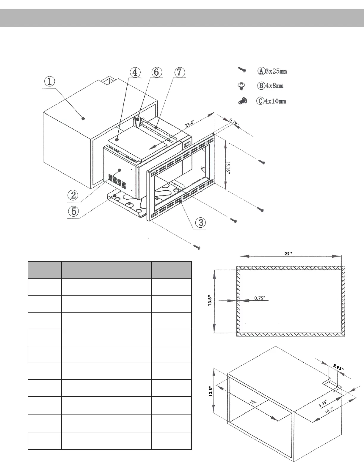
LabelNameQuantity
1Cabinet1
2Microwave Oven1
3Front Grill1
4Upper Exhaust Guide1
5Lower Exhaust Guide1
6Rear Vent Shield1
7Top Vent Shield1
Ⓐ
Screw 3x25mm4
Ⓑ
Screw 4x8mm12
Ⓒ
Screw 4x10mm4
① Cabinet Dimensions
OTR24
INSTALLATION MANUAL
Built-in Microwave
Specyfikacje produktu
| Marka: | Summit |
| Kategoria: | Magnetostrykcja |
| Model: | OTR24 |
Potrzebujesz pomocy?
Jeśli potrzebujesz pomocy z Summit OTR24, zadaj pytanie poniżej, a inni użytkownicy Ci odpowiedzą
Instrukcje Magnetostrykcja Summit

9 Października 2024
30 Września 2024
30 Września 2024
30 Września 2024
30 Września 2024
30 Września 2024
30 Września 2024
30 Września 2024
30 Września 2024
30 Września 2024
Instrukcje Magnetostrykcja
Najnowsze instrukcje dla Magnetostrykcja
9 Kwietnia 2025
9 Kwietnia 2025
8 Kwietnia 2025
8 Kwietnia 2025
8 Kwietnia 2025
8 Kwietnia 2025
7 Kwietnia 2025
7 Kwietnia 2025
7 Kwietnia 2025
7 Kwietnia 2025