Instrukcja obsługi Tripp Lite APSRM4
Tripp Lite Kontroler APSRM4
Przeczytaj poniżej 📖 instrukcję obsługi w języku polskim dla Tripp Lite APSRM4 (2 stron) w kategorii Kontroler. Ta instrukcja była pomocna dla 33 osób i została oceniona przez 2 użytkowników na średnio 4.2 gwiazdek
Strona 1/2
Connecting to an Inverter or Inverter/Charger
Connect one end of the included RJ-type cable into the RJ45 Remote Port on the front of your
PowerVerter Inverter or Inverter/Charger. Connect the other end into either of the two RJ45
Remote Ports on the bottom of the Remote Control Module.
Connecting to Additional Remote Control Modules (Optional)
You can control a single PowerVerter Inverter or Inverter/Charger with two separate Remote
Control Modules. Connect one Remote Control Module directly to the PowerVerter as described
above. Connect either of the two RJ45 Remote Ports on the bottom of the second Remote
Control Module directly to the remaining RJ45 Remote Port on the bottom of the first Remote
Control Module using an RJ-type cable, included.
Connecting to Vehicle's Ignition Switch (Optional)
You can set the Remote Control Module to automatically perform either one of two additional
control functions (DISABLE or ENABLE) by connecting the Remote Control Module to the
vehicle’s ignition switch. These connections are optional; the Remote Control Module will
function without these connections.
“DISABLE” Control Function: This function automatically disables (turns OFF) the AC
power output from the PowerVerter when the vehicle's ignition switch is placed in the
“Engine Run” position. This function will satisfy local codes and requirements concerning
video monitors (or TVs) that are located within a driver’s view by automatically turning
them off when the engine is started.
Using the interface cable* (included with select models), connect the black lead to vehicle
ground (battery negative). Connect the red lead to the “Engine Run” terminal of the
vehicle’s ignition switch. Then, connect the interface cable’s mini-plug to either of two
Ignition Switch Control Jacks located on the side panel of the Remote Control Module: if
you are controlling a PV Inverter, insert the mini-plug into the jack labeled “J-1”; if you are
controlling an APS, RV or EMS Inverter/Charger, insert the mini-plug into the jack labeled
“J-2”. After connecting the interface cable, set the Remote Control Module's switch to
either “ON” (for PV models) or “CHRG ONLY” (for APS, RV or EMS models).
* The interface cable (included with select models) has a mini-plug on one end and two wire leads (one black and one red) on the other.
“ENABLE” Control Function: This function automatically enables (turns ON) the AC
power output from the PowerVerter when the vehicle's ignition switch is placed in either the
“Accessory” or “Engine Run” positions. This function minimizes the risk of discharging the
vehicle battery when the vehicle is parked with the engine off for an extended period of
time.*
Using the interface cable** (included with select models), connect the black lead to vehicle
ground (battery negative). Connect the red lead to the “Accessory” terminal of the vehicle’s
ignition switch. Then, connect the interface cable’s mini-plug to either of two Ignition
Switch Control Jacks located on the side panel of the Remote Control Module: if you are
controlling a PV Inverter, insert the mini-plug into the jack labeled “J-2”; if you are
controlling an APS, RV or EMS Inverter/Charger, insert the mini-plug into the jack labeled
“J-1”. After connecting the interface cable, set the Remote Control Module’s switch to
either “ON” (for PV models) or “CHRG ONLY” (for APS, RV or EMS models).
* Note: a very small discharge current (approximately 18 milliamps) will still exist that should not affect starting ability, even if the
vehicle engine has not been turned on for several days. To reduce this current to zero, set the Remote Control Module’s switch to either
“OFF” (for PV models) or “AUTO” (for APS, RV or EMS models).** The interface cable (included with select models) has a mini-plug
on one end and two wire leads (one black and one red) on the other.
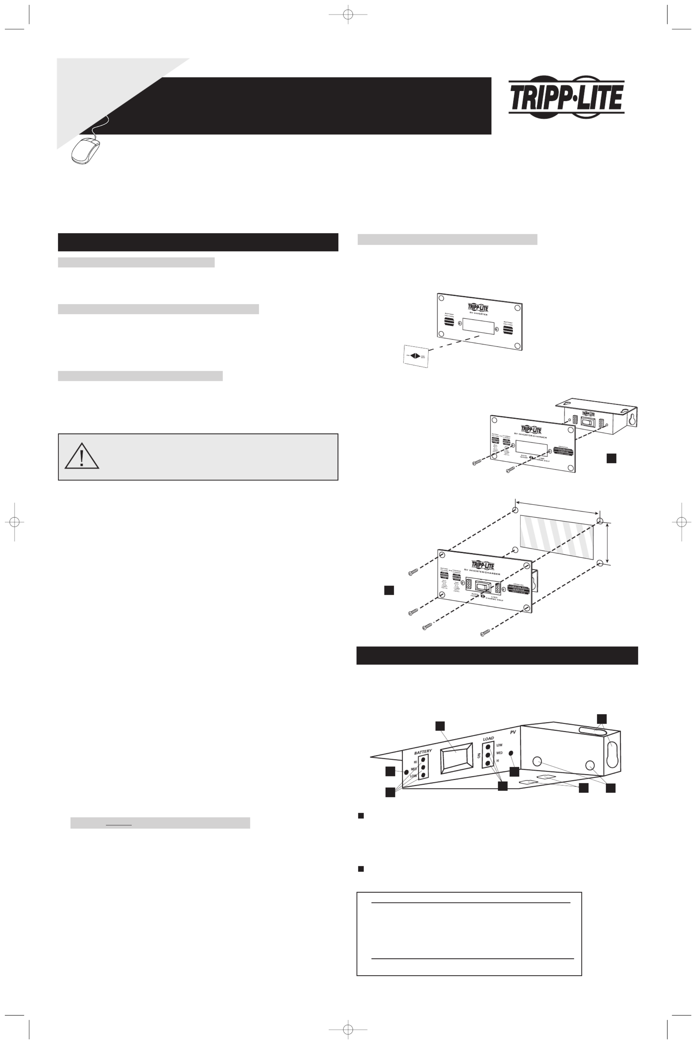
Mounting Without Included Mounting Plate (Optional)
Affix either one of the two included labels to the front panel of the Remote Control Module.
The labels identify the Module's LEDs. Choose the label marked "PV" if you are using the
Remote Control Module to operate a Tripp Lite Inverter. Choose the label market "APS" if
you are using the Remote Control Module to operate a Tripp Lite Inverter/Charger.
Mount the Remote Control Module in a variety of ways (under-counter, recessed, etc.)
using user-supplied hardware inserted through the Module's mounting holes/slots and into
the mounting surface.
Owner’s Manual
Installation
The Remote Control Module allows you to remotely monitor and control many of the functions of select* Tripp Lite PowerVerter PVInverters and PowerVerter
APS, RV or EMS Inverter/Chargers.
* Only those models featuring an RJ45 Remote Port.
WARNING! THE IGNITION SWITCH CONTROL FUNCTION IS
ONLY FOR USE WITH 12V NEGATIVE GROUND SYSTEMS.
Wiring the Ignition Switch Control Cable to your vehicle’s ignition requires a
qualified technician, who must determine the proper wiring procedure.
1111 W. 35th Street Chicago, IL 60609 USA
Customer Support: (773) 869-1234 • www.tripplite.com
Operation
Mounting with Included Mounting Plate (Optional)
• For PVXXXXHF Model Inverters: Install with Inverter side of plate facing out.
• For PVXXXXFC Model Inverters: Install with Inverterside of plate facing out;
place included label on plate as shown.
• For Inverter/Chargers (All Models): Install with Inverter/Charger side of plate facing out.
STEP 1)Using the two included
machine screws, attach the
Mounting Plate to the front of the
Remote Control Module.
STEP 2) Using the four included
sheet metal screws, install the
Mounting Plate and Remote
Control Module in the panel
opening of your vehicle.
5.25 in. (13.335 cm.)
3.25 in
(8.255 cm.)
Choose operation based on whether you connect your Remote Control Module to an Inverter
(PV series) or Inverter/Charger (APS, RV or EMS series).
INVERTER (PV series)
OFF/ON Switch:
Move this switch to the “ON” position to have your Inverter provide connected equipment
with AC power by converting DC power from an attached battery.
To prevent battery drain, leave it in the “OFF” or “INV OFF”* position when not using
connected equipment.
“BATTERY” LEDs: These three lights show the approximate charge of your
connected batteries. See chart below for approximate charges.
LEDs Illuminated Approximate Charge
Green96% - Full
Green & yellow81% - 95%
Yellow61% - 80%
Yellow & red41% - 60%
Red21% - 40%
All three lights off1% - 20%
Flashing red0% (Inverter shutdown)
All three lights flash slowlyExcessive discharge
All three lights flash quicklyOvercharge
* “OFF” when used with lable; “INV OFF” when used with mounting plate.
2
1
J1
J2
OFF
1
2
34 5
6
6
6
Module shown without mounting plate
WARRANTY
REGISTRATION:
register online today for a
chance to win a FREE Tripp Lite
product—www.tripplite.com/warranty
Remote Control Module & Mounting Plate
for use with select PowerVerter®Inverters (PV series) or PowerVerter
®Inverter/Chargers (APS, RV or EMS series)
LO W
LO W
M ED I UM
M ED I U M
HIG
H
HIG
H
Placement of Label
1
2
200603011--APSRM2 Owner’s Manual Update.qxd 3/24/2006 3:22 PM Page 1
Specyfikacje produktu
| Marka: | Tripp Lite |
| Kategoria: | Kontroler |
| Model: | APSRM4 |
Potrzebujesz pomocy?
Jeśli potrzebujesz pomocy z Tripp Lite APSRM4, zadaj pytanie poniżej, a inni użytkownicy Ci odpowiedzą
Instrukcje Kontroler Tripp Lite

12 Września 2024
Instrukcje Kontroler
Najnowsze instrukcje dla Kontroler
2 Kwietnia 2025
30 Marca 2025
30 Marca 2025
30 Marca 2025
30 Marca 2025
30 Marca 2025
28 Marca 2025
27 Marca 2025
26 Marca 2025
2 Marca 2025