Instrukcja obsługi Yato YT-0770
Yato Maszyna do śrub YT-0770
Przeczytaj poniżej 📖 instrukcję obsługi w języku polskim dla Yato YT-0770 (2 stron) w kategorii Maszyna do śrub. Ta instrukcja była pomocna dla 16 osób i została oceniona przez 2 użytkowników na średnio 4.4 gwiazdek
Strona 1/2
KLUCZ DYNAMOMETRYCZNY
TORQUE WRENCH
DREHMOMENTSCHLÜSSEL
КЛЮЧДИНАМОМЕТРИЧЕСКИЙ
КЛЮЧДИНАМОМЕТРИЧНИЙ
DINAMOMETRINIS RAKTAS
GRIEZES MOMENTA ATSLĒGA
MOMENTOVÝ KLÍČ
MOMENTOVÝ KĹÚČ
NYOMATÉKKULCS
CHEIE DINAMOMETRICĂ
LLAVE DINAMOMÉTRICA
CLÉ DYNAMOMÉTRIQUE
CHIAVE DINAMOMETRICA
MOMENTSLEUTEL
ΔΥΝΑΜΟΚΛΕΙΔΟ
ДИНАМОМЕТРИЧЕНКЛЮЧ
CHAVE DINAMOMÉTRICA
MOMENT KLJUČ
مزﻌﻟاحﺎﺗﻔﻣ
CHARAKTERYSTYKA NARZĘDZIA
Klucz dynamometryczny jest precyzyjnym instrumentem stosowanym do uzyskiwania określonego
momentu obrotowego. Służy do skręcania części złącznych gwintowanych tak, aby moment obrotowy
połączenia był znany i odpowiedni do rodzaju materiału i wytrzymałości śruby i nakrętki.
Zestawienie porównawcze momentów w różnych jednostkach długości i siły:
1 kG*cm = 13,887 OZ*IN (uncja x cal)
1 kG*cm = 0,867 LB*IN (funt x cal)
1kG*m = 9,80665 N*m (Niuton x metr)
1 kG*m = 7,233 LB*FT (funt x stopa)
1FT*LB = 12 LB*IN (funt x cal)
1dm*N = 14,16 OZ*IN (uncja x cal)
Indeks
Rozmiar
zabieraka
Moment obrotowy [Nm]
Długość [mm]
Min.Max.
YT-07509,5 mm; 3/8”20110342-360
YT-076012,7 mm; 1/2”42210445-465
YT-076112,7 mm; 1/2”40210516-534
YT-0770 19 mm; 3/4”100500845-860
YT-077119 mm; 3/4”1409801215-1230
OBSŁUGA KLUCZA
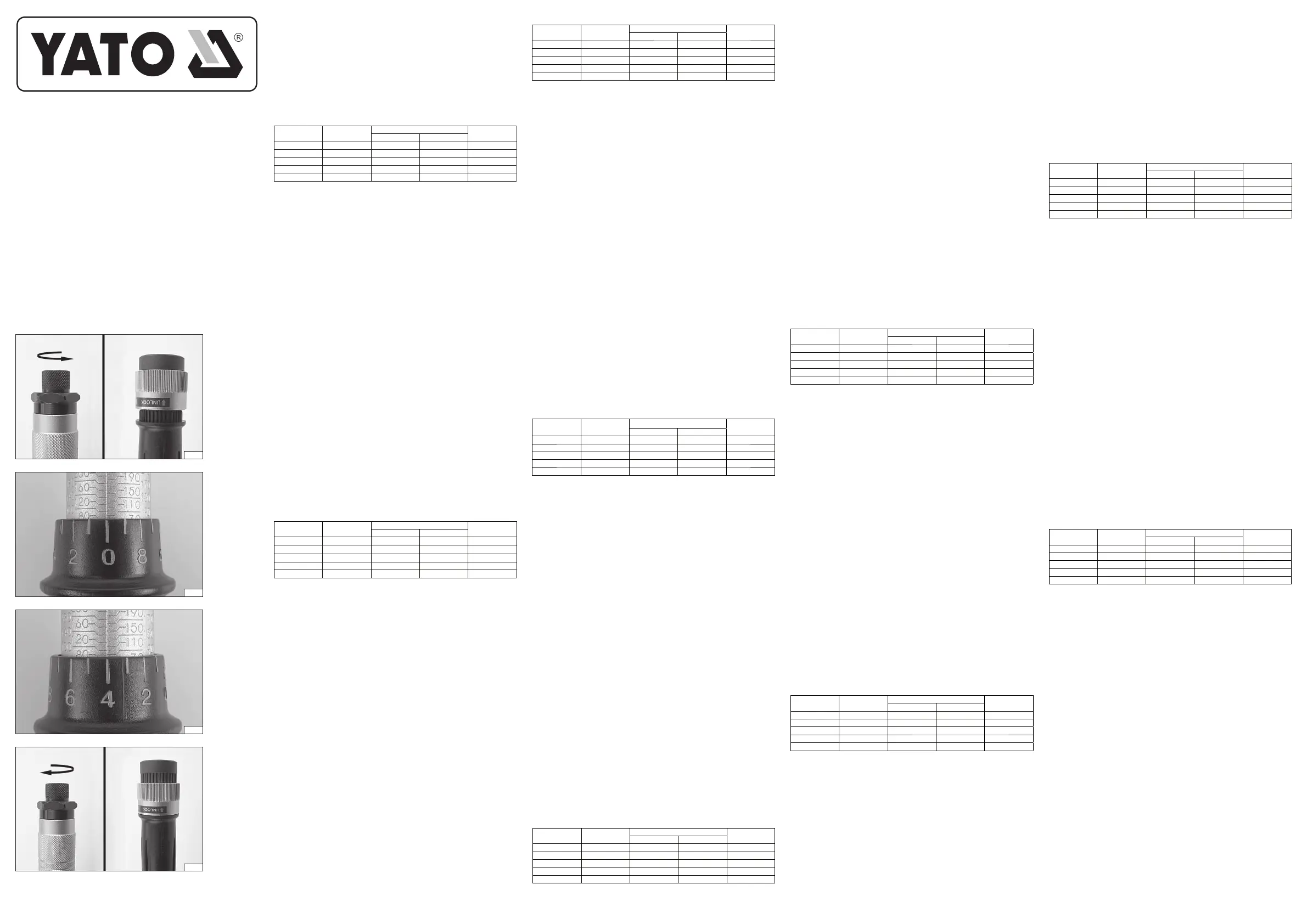
Wybrać odpowiednią skalę Nm lub in-lbs. Odblokować pokrętło mikrometryczne (I).
Pokrętło mikrometryczne ustawić tak, aby „0” na skali pokrętła pokryło się z pionową linią na ramieniu
klucza (II).
Pokrętło mikrometryczne obracać zgodnie z kierunkiem ruchu wskazówek zegara, do momentu
ustawienia żądanego momentu obrotowego. Żądany moment obrotowy jest ustawiony w momencie, gdy
podziałka na pokrętle mikrometrycznym będzie się pokrywała z pionową linią na ramieniu klucza. (III)
Następnie należy zablokować pokrętło mikrometryczne (IV) oraz ustawić odpowiedni kierunek obrotu
grzechotki, po tym klucz jest gotowy do użytku.
Na zabierak klucza należy nałożyć odpowiednią
nasadkę. Podczas dokręcania osiągnięcie ustawionego
momentu jest sygnalizowane przełamaniem się głowicy klucza. W przypadku wyczucia przełamania
głowicy należy zaprzestać dokręcania.
Uwaga! Nie wolno kontynuować dokręcania śrub po tym jak klucz zasygnalizuje nastawiony moment
obrotowy. Należy na to zwrócić szczególną uwagę podczas dokręcania z niewielkimi momentami.
Nie wolno nastawiać wartości momentu spoza zakresu pomiarowego klucza.
Uwaga! Nie wolno stosować, żadnych przedłużeń klucza, w celu wydłużenia ramienia, do którego
przykładana jest siła. Na przykład przez zastosowanie dodatkowej rury przedłużającej.
KONSERWACJA KLUCZA
Jeśli klucz nie będzie używany przez dłuższy czas należy nastawić minimalny zakres.
Nie należy wykręcać pokrętła mikrometrycznego poniżej nastawy najniższego momentu.
Klucz wolno czyścić jedynie sucha miękka bawełnianą szmatką. Nie wolno używać jakichkolwiek
rozpuszczalników, czy innych cieczy. Gdyż mogą one wypłukać smar, którym fabrycznie jest
nasmarowany mechanizm klucza.
Klucz jest wykalibrowany fabrycznie z dokładnością do 4%. Do klucza dołączono fabryczne świadectwo
kalibracji klucza. Świadectwo należy zachować, nie istnieje możliwość wystawienia duplikatu
zagubionego świadectwa kalibracji.
TOOL CHARACTERISTICS
A torque wrench is a precision instrument used to obtain a specific torque. It is used to tighten threaded
fasteners so that the torque of the connection is known and appropriate for the type of material and
strength of the bolt and nut.
Comparison of moments in diff erent units of length and force:
1 kg * cm = 13.887 OZ * IN (ounce x inch)
1 kg *cm = 0.867 LB*IN (lb x in)
1kG*m = 9.80665 N*m (Newton x meter)
1 kg * m = 7.233 LB * FT (lb x ft)
1FT*LB = 12 LB*IN (lb x inch)
1dm*N = 14.16 OZ*IN (ounce x inch)
IndexDriver size
Torque [ Nm ]
Length [mm]
Min.Max.
YT-07509,5 mm; 3/8”20110342-360
YT-076012,7 mm; 1/2”42210445-465
YT-076112,7 mm; 1/2”40210516-534
YT-077019 mm; 3/4”100500845-860
YT-077119 mm; 3/4”1409801215-1230
KEY OPERATION
Select the appropriate scale Nm or in- lbs . Unlock the micrometer knob (I).
Set the micrometer knob so that „0” on the knob scale aligns with the vertical line on the key arm (II).
Turn the micrometer knob clockwise until the desired torque is set. The desired torque is set when the
scale on the micrometer knob aligns with the vertical line on the wrench arm. (III)
Then, lock the micrometer knob (IV) and set the appropriate direction of rotation of the ratchet, after which
the wrench is ready for use.
The appropriate cap should be placed on the key driver. During tightening, reaching the set torque is
signaled by the head of the key breaking. If you feel the head breaking, stop tightening.
Attention! Do not continue to tighten the screws after the wrench signals the set torque. Pay particular
attention to this when tightening with low torques.
Do not set a torque value outside the measuring range of the wrench.
Note! No extensions of the wrench may be used to extend the arm to which the force is applied. For
example, by using an additional extension tube.
KEY MAINTENANCE
If the key will not be used for a long time, set the minimum range.
Do not turn the micrometer knob beyond the lowest torque setting.
The key may only be cleaned with a dry, soft cotton cloth. Do not use any solvents or other liquids. They
may wash out the grease that is factory-lubricated in the key mechanism.
The key is factory calibrated to an accuracy of 4%. The key is supplied with a factory key calibration
certifi cate. The certificate should be retained, it is not possible to issue a duplicate of a lost calibration
certifi cate.
YT-0750
YT-0760
YT-0761
YT-0770
YT-0771
PL
EN
RU
UA
LT
LV
SK
HU
CZ
DE
PL
EN
DE
RU
UA
LT
LV
CZ
SK
HU
RO
ES
FR
IT
NL
GR
BG
PT
HR
AR
WERKZEUGMERKMALE
Ein Drehmomentschlüssel ist ein Präzisionsinstrument zum Erreichen eines bestimmten Drehmoments.
Er dient zum Festziehen von Gewindeverbindungen, sodass das Drehmoment der Verbindung bekannt
und für Materialart und Festigkeit von Schraube und Mutter geeignet ist.
Vergleich von Momenten in verschiedenen Längen- und Krafteinheiten:
1 kg * cm = 13,887 OZ * IN (Unze x Zoll)
1 kg * cm = 0,867 LB * IN (lb x in)
1 kG*m = 9,80665 N*m (Newton x Meter)
1 kg * m = 7,233 LB * FT (lb x ft)
1FT*LB = 12 LB*IN (lb x Zoll)
1dm*N = 14,16 OZ*IN (Unze x Zoll)
IndexTreibergröße
Drehmoment [ Nm ]
Länge [mm]
Mindest.Max.
YT-07509,5 mm; 3/8”20110342-360
YT-076012,7 mm; 1/2”42210445-465
YT-076112,7 mm; 1/2”40210516-534
YT-077019 mm; 3/4”100500845-860
YT-077119 mm; 3/4”1409801215-1230
TASTENBEDIENUNG
Wählen Sie die entsprechende Skala Nm oder in- lbs . Entriegeln Sie den Mikrometerknopf (I).
Stellen Sie den Mikrometerknopf so ein, dass die „0“ auf der Knopfskala mit der vertikalen Linie auf dem
Tastenarm (II) übereinstimmt.
Drehen Sie den Mikrometerknopf im Uhrzeigersinn, bis das gewünschte Drehmoment eingestellt ist. Das
gewünschte Drehmoment ist eingestellt, wenn die Skala am Mikrometerknopf mit der vertikalen Linie am
Schlüsselarm übereinstimmt. (III)
Anschließend wird der Mikrometerknopf (IV) verriegelt und die entsprechende Drehrichtung der Ratsche
eingestellt, danach ist der Schlüssel einsatzbereit.
Die passende Kappe sollte auf den Schlüsseldreher aufgesetzt werden. Beim Anziehen wird das
Erreichen des eingestellten Drehmoments durch das Abbrechen des Schlüsselkopfes signalisiert. Sobald
Sie spüren, dass der Kopf abbricht, brechen Sie den Anziehvorgang ab.
Achtung! Ziehen Sie die Schrauben nicht weiter an, nachdem der Schlüssel das eingestellte Drehmoment
signalisiert. Beachten Sie dies insbesondere bei niedrigen Drehmomenten.
Stellen Sie keinen Drehmomentwert außerhalb des Messbereichs des Schlüssels ein.
Hinweis! Zur Verlängerung des Kraftangriff sarms dürfen keine Verlängerungen des Schlüssels verwendet
werden. Beispielsweise durch ein zusätzliches Verlängerungsrohr.
WICHTIGE WARTUNG
Wenn der Schlüssel längere Zeit nicht verwendet wird, stellen Sie die Mindestreichweite ein.
Drehen Sie den Mikrometerknopf nicht über die niedrigste Drehmomenteinstellung hinaus.
Die Taste darf nur mit einem trockenen, weichen Baumwolltuch gereinigt werden. Verwenden Sie
keine Lösungsmittel oder andere Flüssigkeiten. Diese könnten das werkseitig im Tastenmechanismus
eingebrachte Schmierfett auswaschen.
Der Schlüssel ist werkseitig auf eine Genauigkeit von 4 % kalibriert. Der Schlüssel wird mit einem
Werkskalibrierungszertifikat geliefert. Das Zertifikat sollte aufbewahrt werden. Bei Verlust kann kein
Duplikat ausgestellt werden.
ХАРАКТЕРИСТИКИИНСТРУМЕНТА
Динамометрическийключ — этоточный инструмент, используемый для получения определенного
крутящегомомента. Ониспользуетсядлязатягиваниярезьбовыхсоединений, чтобымомент
затяжкисоединениябылизвестенисоответствовалтипуматериалаипрочностиболтаигайки.
Сравнениемоментоввразличныхединицах
длиныисилы:
1 кг * см = 13,887 OZ * IN (унция x дюйм)
1 кг * см = 0,867 ФУНТ*ДЮЙМ (фунт x дюйм)
1кГс*м = 9,80665 Н*м (Ньютон x метр)
1 кг * м = 7,233 ФУНТ * ФУТ (фунт x фут)
1 фут*фунт = 12 фунтов*дюймов (фунт x дюйм)
1 дм*Н = 14,16 OZ*IN (унция x дюйм)
Индекс
Размер
драйвера
Крутящиймомент [ Нм ]
Длина [мм]
Мин.Макс.
YT-07509,5 мм; 3/8”20110342-360
YT-076012,7 мм; 1/2”42210445-465
YT-076112,7 мм; 1/2”40210516-534
YT-077019 мм; 3/4”100500845-860
YT-077119 мм; 3/4”1409801215-1230
КЛЮЧЕВАЯОПЕРАЦИЯ
ВыберитесоответствующуюшкалуНмилидюйм -фунт . Разблокируйтеручкумикрометра (I).
Установитеручкумикрометратак, чтобыотметка «0» нашкалеручкисовпадаласвертикальной
линиейнарычагеключа (II).
Поворачивайтеручкумикрометрапочасовойстрелке, пока
не будетустановленжелаемый
крутящиймомент. Желаемый крутящий момент установлен, когдашкала на ручке микрометра
совпадаетсвертикальнойлиниейнарычагеключа. (III)
Затемзафиксируйтеручкумикрометра (IV) иустановитесоответствующеенаправлениевращения
храповогомеханизма, послечегоключготов к использованию.
Наворотокключаследуетнадетьсоответствующийколпачок. Вовремязатяжкидостижение
установленногомоментазатяжкисигнализируетсяполомкойголовкиключа. Есливычувствуете,
чтоголовкаломается, прекратитезатяжку.
Внимание! Непродолжайтезатягиватьвинтыпослетого, какключподастсигналозаданном
крутящеммоменте. Обратитенаэтоособоевниманиепризатягиванииснизкимкрутящим
моментом.
Неустанавливайтезначениекрутящегомомента, выходящеезапределыдиапазонаизмерения
гаечногоключа.
Примечание! Дляудлиненияруки, ккоторойприкладываетсясила, нельзяиспользовать
удлинителиключа. Например, с помощью дополнительнойудлинительнойтрубки.
ОБСЛУЖИВАНИЕКЛЮЧЕЙ
Еслиключне будетиспользоватьсявтечениедлительноговремени, установитеминимальный
диапазон.
Неповорачивайтеручкумикрометраза пределыминимальногокрутящегомомента.
Чиститьключможнотолькосухоймягкойхлопчатобумажнойтканью. Неиспользуйтерастворители
илидругиежидкости. Онимогутвымытьсмазку, которая была заложена на заводе в механизм
ключа.
Ключоткалиброванназаводесточностью 4%. Ключпоставляетсясзаводскимсертификатом
калибровкиключа. Сертификатнеобходимосохранить, выдачадубликатаутерянногосертификата
калибровкиневозможна.
ХАРАКТЕРИСТИКИІНСТРУМЕНТУ
Динамометричнийключ – цепрецизійнийінструмент, який використовується для отримання
певногокрутногомоменту. Він використовується для затягування різьбових кріплень таким чином,
щобкрутний момент з’єднання буввідомим і відповідав типу матеріалутаміцності болтатагайки.
Порівняннямоментівурізниходиницяхдовжинитасили:
1 кг * см = 13,887 OZ * IN (унція х дюйм)
1 кг * см = 0,867 фунта * дюйм (фунт x дюйм)
1 кГ*м = 9,80665 Н
*м (Ньютон х метр)
1 кг * м = 7,233 фунта * фути (фунт x фут)
1 фут*фунт = 12 фунт*дюйм (фунт x дюйм)
1 дм*N = 14,16 OZ*IN (унція х дюйм)
Індекс
Розмір
драйвера
Крутниймомент [ Нм ]
Довжина [мм]
Хв.Макс.
YT-07509,5 мм; 3/8”20110342-360
YT-076012,7 мм; 1/2”42210445-465
YT-076112,7 мм; 1/2”40210516-534
YT-077019 мм; 3/4”100500845-860
YT-077119 мм; 3/4”1409801215-1230
КЛЮЧОВАОПЕРАЦІЯ
ВиберітьвідповіднушкалувНмабодюймах -фунтах . Розблокуйтеручкумікрометра (I).
ĮRANKIO CHARAKTERISTIKOS
Sukimo momento veržliaraktis yra tikslus instrumentas, naudojamas konkrečiam sukimo momentui gauti.
Jis naudojamas srieginėms tvirtinimo detalėms priveržti, kad jungties sukimo momentas būtų žinomas ir
atitiktų varžto ir veržlės medžiagos tipą bei stiprumą.
Momentų palyginimas skirtingais ilgio ir jėgos vienetais:
1 kg * cm = 13,887 OZ * IN (uncija x colis)
1 kg *cm = 0,867 LB*IN (svaras x colis)
1kG*m = 9,80665 N*m (Niutonas x metras)
1 kg * m = 7,233 svaro * pėdos (svaras x pėda)
1FT*LB = 12 LB*IN (lb x colyje)
1 dm*N = 14,16 OZ*IN (uncija x colis)
IndeksasVairuotojo dydis
Sukimo momentas [ Nm ]
Ilgis [mm]
Min.Maks.
YT-07509,5 mm; 3/8”20110342–360
YT-076012,7 mm; 1/2”42210445–465
YT-076112,7 mm; 1/2”40210516–534
YT-077019 mm; 3/4”100500845–860
YT-077119 mm; 3/4”1409801215–1230
PAGRINDINIS OPERACIJA
Pasirinkite tinkamą skalę Nm arba in- lbs . Atblokuokite mikrometro rankenėlę (I).
Nustatykite mikrometro rankenėlę taip, kad „0“ ant rankenėlės skalės sutaptų su vertikalia linija ant rakto
svirties (II).
Sukite mikrometro rankenėlę pagal laikrodžio rodyklę, kol bus nustatytas norimas sukimo momentas.
Norimas sukimo momentas nustatytas, kai mikrometro rankenėlės skalė sutampa su vertikalia linija ant
veržliarakčio rankenos. (III)
Tada užfiksuokite mikrometro rankenėlę (IV) ir nustatykite tinkamą reketo sukimosi kryptį, po to raktas
bus paruoštas naudoti.
Ant rakto atsuktuvo reikia uždėti atitinkamą dangtelį. Priveržimo metu pasiekus nustatytą sukimo
momentą, lūžta rakto galvutė. Jei pajuntate, kad galvutė lūžta, nustokite veržti.
Dėmesio! Veržliarakčiui pasiekus nustatytą sukimo momentą, varžtų nebeveržkite. Į tai atkreipkite
ypatingą dėmesį, kai veržiama mažu sukimo momentu.
Nenustatykite sukimo momento vertė
s, esančios už veržliarakčio matavimo diapazono ribų.
Pastaba! Negalima naudoti jokių veržliarakčio prailginimų rankai, kuriai taikoma jėga, pailginti. Pavyzdžiui,
negalima naudoti papildomo prailginimo vamzdžio.
PAGRINDINĖ PRIEŽIŪRA
Jei raktas ilgą laiką nebus naudojamas, nustatykite minimalų diapazoną.
Nesukite mikrometro rankenėlės aukščiau mažiausio sukimo momento nustatymo.
Raktą galima valyti tik sausa, minkšta medvilnine šluoste. Nenaudokite jokių tirpiklių ar kitų skysčių. Jie
gali išplauti tepalą, kuris gamykloje sutepamas rakto mechanizme.
Raktas yra kalibruotas gamykloje 4 % tikslumu. Raktas pateikiamas su gamykliniu rakto kalibravimo
sertifi katu. Sertifi katą reikia išsaugoti, pamesto kalibravimo sertifikato dublikato išduoti negalima.
INSTRUMENTU RAKSTUROJUMS
Griezes momenta atslēga ir precīzs instruments, ko izmanto, lai iegūtu noteiktu griezes momentu. To
izmanto, lai pievilktu vītņotus stiprinājumus, lai savienojuma griezes moments būtu zināms un atbilstošs
skrūves un uzgriežņa materiāla veidam un stiprībai.
Momentu salīdzinājums dažādās garuma un spēka mērvienībās:
1 kg * cm = 13,887 unces * collas (unce x colla)
1 kg *cm = 0,867 LB*IN (mārciņas x collas)
1kG*m = 9,80665 N*m (ņūtons x metrs)
1 kg * m = 7,233 mārciņas * pēdas (mārciņas x pēdas)
1FT*LB = 12 LB*IN (mārciņas x collas)
1 dm*N = 14,16 OZ*IN (unce x colla)
IndekssVadītāja izmērs
Griezes moments [ Nm ]
Garums [mm]
Min.Maks.
YT-07509,5 mm; 3/8”20110342–360
YT-076012,7 mm; 1/2”42210445–465
YT-076112,7 mm; 1/2”40210516–534
YT-077019 mm; 3/4”100500845–860
YT-077119 mm; 3/4”1409801215–1230
GALVENĀ DARBĪBA
Izvēlieties atbilstošo skalu Nm vai in- lbs . Atbloķējiet mikrometra pogu (I).
Iestatiet mikrometra pogu tā, lai „0” uz pogas skalas sakristu ar vertikālo līniju uz atslēgas sviras (II).
Grieziet mikrometra pogu pulksteņrādītāja virzienā, līdz ir iestatīts vēlamais griezes moments. Vēlamais
griezes moments ir iestatīts, kad mikrometra pogas skala sakrīt ar vertikālo līniju uz atslēgas sviras. (III)
Pēc tam nofi ksējiet mikrometra pogu (IV) un iestatiet atbilstošo sprūdrata griešanās virzienu, pēc tam
uzgriežņu atslēga ir gatava lietošanai.
Uz atslēgas skrūvēm jāuzliek atbilstošais vāciņš. Pievilkšanas laikā par iestatītā griezes momenta
sasniegšanu signalizē
atslēgas galviņas salūšana. Ja jūtat, ka galviņa salūzt, pārtrauciet pievilkšanu.
Uzmanību! Neturpiniet pievilkt skrūves pēc tam, kad uzgriežņu atslēga signalizē par iestatīto griezes
momentu. Pievērsiet tam īpašu uzmanību, pievelkot ar mazu griezes momentu.
Neiestatiet griezes momenta vērtību ārpus atslēgas mērīšanas diapazona.
Piezīme! Atslēgas pagarinājumus nedrīkst izmantot, lai pagarinātu roku, uz kuru tiek pielikts spēks.
Piemēram, izmantojot papildu pagarinātāja cauruli.
GALVENĀ APKOPE
Ja atslēga netiks izmantota ilgu laiku, iestatiet minimālo diapazonu.
CHARAKTERISTIKA NÁSTROJE
Momentový klíč je přesný nástroj používaný k dosažení specifického krouticího momentu. Používá se
k utahování závitových spojů tak, aby byl krouticí moment spoje známý a vhodný pro typ materiálu a
pevnost šroubu a matice.
Porovnání momentů v různých jednotkách délky a síly:
1 kg * cm = 13,887 OZ * IN (unce x palec)
1 kg * cm = 0,867 LB*PALCŮ (libry x palce)
1 kG*m = 9,80665 N*m (Newton x metr)
1 kg * m = 7,233 LB * FT (libry x stopy)
1 stopa*libra = 12 lb*palec (libra x palec)
1dm*N = 14,16 OZ*IN (unce x palec)
Index
Velikost ovla-
dače
Točivý moment [ Nm ]
Délka [mm]
Min.Max.
YT-07509,5 mm; 3/8”20110342–360
YT-076012,7 mm; 1/2”42210445–465
YT-076112,7 mm; 1/2”40210516–534
YT-077019 mm; 3/4”100500845–860
YT-077119 mm; 3/4”1409801215-1230
KLÍČOVÁ FUNKCE
Vyberte vhodnou stupnici v Nm nebo in- lbs . Odemkněte knoflík mikrometru (I).
Nastavte mikrometrický knofl ík tak, aby se „0“ na stupnici knoflíku shodovala se svislou čarou na rameni
klíče (II).
Otáčejte knoflíkem mikrometru ve směru hodinových ručiček, dokud nenastavíte požadovaný utahovací
moment. Požadovaný utahovací moment je nastaven, když se stupnice na knofl íku mikrometru srovná
se svislou čarou na rameni klíče. (III)
Poté zajistěte mikrometrickou knoflík (IV) a nastavte vhodný směr otáčení ráčny, po kterém je klíč
připraven k použití.
Na klíčový klíč by měla být nasazena příslušná krytka. Během utahování je dosažení nastaveného
momentu signalizováno zlomením hlavy klíče. Pokud cítíte, že se hlava zlomila, přestaňte utahovat.
Pozor! Nepokračujte v utahování šroubů poté, co klíč signalizuje nastavený moment. Věnujte tomu
zvláštní pozornost při utahování nízkými momenty.
Nenastavujte hodnotu točivého momentu mimo měř
icí rozsah klíče.
Poznámka! K prodloužení ramene, na které působí síla, se nesmí použít žádné prodlužovací části klíče.
Například použitím dodatečné prodlužovací trubky.
KLÍČOVÁ ÚDRŽBA
Pokud klíč nebudete delší dobu používat, nastavte minimální dosah.
Neotáčejte mikrometrickou knofl íkkou za nejnižší nastavení utahovacího momentu.
Klíč smí být čištěn pouze suchým, měkkým bavlněným hadříkem. Nepoužívejte žádná rozpouštědla ani
jiné tekutiny. Mohly by vymýt mazivo, které je v mechanismu klíče naneseno z výroby.
Klíč je z výroby kalibrován s přesností 4 %. Klíč je dodáván s kalibračním certifi kátem z výroby. Certifi kát
je třeba uschovat, není možné vydat duplikát ztraceného kalibračního certifi kátu.
CHARAKTERISTIKA NÁSTROJA
Momentový kľúč je presný nástroj používaný na dosiahnutie špecifického krútiaceho momentu. Používa
sa na uťahovanie závitových spojovacích prvkov tak, aby bol krútiaci moment spoja známy a vhodný pre
typ materiálu a pevnosť skrutky a matice.
Porovnanie momentov v rôznych jednotkách dĺžky a sily:
1 kg * cm = 13,887 OZ * IN (unca x palec)
1 kg * cm = 0,867 LB*IN (libra x palec)
1 kG*m = 9,80665 N*m (Newton x meter)
1 kg * m = 7,233 LB * FT (libry x stopy)
1 stopa*libra = 12 libier*palec (libra x palec)
1dm*N = 14,16 OZ*IN (unca x palec)
IndexVeľkosť vodiča
Krútiaci moment [ Nm ]
Dĺžka [mm]
Min.Max.
YT-07509,5 mm; 3/8”20110342 – 360
YT-076012,7 mm; 1/2”42210445 – 465
YT-076112,7 mm; 1/2”40210516 – 534
YT-077019 mm; 3/4”100500845 – 860
YT-077119 mm; 3/4”1409801215 – 1230
OVLÁDANIE KLÁVESOV
Vyberte príslušnú stupnicu v Nm alebo v palcoch a librách . Odomknite gombík mikrometra (I).
Nastavte mikrometrické koliesko tak, aby sa hodnota „0“ na stupnici kolieska zhodovala so zvislou čiarou
na ramene kľúča (II).
Otáčajte mikrometrickým kolieskom v smere hodinových ručičiek, kým nenastavíte požadovaný krútiaci
moment. Požadovaný krútiaci moment je nastavený, keď sa stupnica na mikrometrickom koliesku
zarovná so zvislou čiarou na ramene kľúča. (III)
Potom zablokujte mikrometrické koliesko (IV) a nastavte vhodný smer otáčania račňového kľúča, po čom
je kľúč pripravený na použitie.
Na kľúčový kľúč by mala byť nasadená príslušná krytka. Počas uťahovania je dosiahnutie nastaveného
krútiaceho momentu signalizované zlomením hlavy kľúča. Ak cítite, že sa hlava zlomila, prestaňte
uťahovať.
Pozor! Nepokračujte v uťahovaní skrutiek po tom, čo kľúč signalizuje nastavený krútiaci moment. Venujte
tomu zvláštnu pozornosť pri uťahovaní s nízkymi krútiacimi momentmi.
Nenastavujte hodnotu krútiaceho momentu mimo meracieho rozsahu kľúča.
Poznámka! Na predĺženie ramena, na ktoré pôsobí sila, sa nesmú použiť žiadne predĺženia kľúča.
Napríklad použitím dodatočnej predlžovacej trubice.
KLÚČOVÁ ÚDRŽBA
Ak sa kľúč nebude dlhší čas používať, nastavte minimálny dosah.
Neotáčajte mikrometrickým gombíkom za najnižšiu hodnotu krútiaceho momentu.
Kľúč sa smie čistiť iba suchou, mäkkou bavlnenou handričkou. Nepoužívajte žiadne rozpúšťadlá ani iné
tekutiny. Môžu vymyť mazivo, ktoré je namazané z výroby v mechanizme kľúča.
Kľúč je kalibrovaný z výroby s presnosťou 4 %. Kľúč sa dodáva s certifikátom o kalibrácii z výroby.
Certifi kát si uschovajte, nie je možné vydať duplikát strateného kalibračného certifi kátu.
SZERSZÁM JELLEMZŐI
A nyomatékkulcs egy precíziós eszköz, amelyet egy adott nyomaték elérésére használnak. Menetes
rögzítőelemek meghúzására szolgál, hogy a csatlakozás nyomatéka ismert és megfelelő legyen a csavar
és anya anyagának és szilárdságának.
A nyomatékok összehasonlítása különböző hosszúság- és erőegységekben:
1 kg * cm = 13,887 OZ * IN (uncia x hüvelyk)
1 kg *cm = 0,867 LB*IN (lb x in)
1kG*m = 9,80665 N*m (Newton x méter)
1 kg * m = 7,233 font * láb (font x láb)
1 láb*font = 12 font*hüvelyk (font x hüvelyk)
1dm*N = 14,16 OZ*IN (uncia x hüvelyk)
Встановітьручкумікрометратак, щобпозначка «0» нашкаліручкизбігаласязвертикальноюлінією
накронштейніключа (II).
Повертайтеручкумікрометразагодинниковоюстрілкою, докинебудевстановленопотрібний
крутниймомент. Потрібний крутний момент встановлено, коли шкала на ручці мікрометра
збігаєтьсязвертикальноюлінієюнакронштейніключа. (III)
Потімзафіксуйтеручкумікрометра (IV) тавстановітьвідповіднийнапрямокобертанняхраповика,
післячогоключготовийдовикористання.
Наключ-головкусліднадітивідповіднийковпачок. Підчасзатягуваннядосягненнявстановленого
крутногомоментусигналізуєтьсятим, щоголовкаключаламається. Якщо ви відчуваєте, що
головкаламається, припинітьзатягування.
Увага! Непродовжуйтезатягуватигвинтипіслятого, як гайковий ключсигналізує провстановлений
моментзатягування. Звернітьна
це особливуувагупідчасзатягуваннязнизькимимоментами
затягування.
Невстановлюйтезначеннякрутногомоментупозамежамидіапазонувимірюванняключа.
Примітка! Длявисуванняважеля, доякогоприкладаєтьсясила, неможнавикористовувати
подовжувачігайковогоключа. Наприклад, за допомогою додатковоїподовжувальноїтрубки.
КЛЮЧОВЕТЕХНІЧНЕОБСЛУГОВУВАННЯ
Якщоключне використовуватиметьсяпротягомтривалогочасу, встановіть мінімальну дальність.
Неповертайтеручкумікрометравищенайнижчогозначеннякрутногомоменту.
Ключможначиститилишесухоюм’якоюбавовняноютканиною. Невикористовуйтерозчинникичи
іншірідини. Вониможутьзмитимастило, якеєзаводськиммастиломумеханізміключа.
Ключвідкаліброваноназаводізточністю 4%. Ключпостачаєтьсяіззаводськимсертифікатом
калібруванняключа. Сертифікатслідзберігати, дублікатвтраченогосертифікатакалібрування
видатинеможливо.
Negrieziet mikrometra pogu tālāk par zemāko griezes momenta iestatījumu.
Atslēgu drīkst tīrīt tikai ar sausu, mīkstu kokvilnas drānu. Nelietojiet šķīdinātājus vai citus šķidrumus. Tie
var izskalot atslēgas mehānismā rūpnīcā ieeļļoto smērvielu.
Atslēga ir rūpnīcā kalibrēta ar 4 % precizitāti. Atslēgai ir pievienots rūpnīcas atslēgas kalibrēšanas
sertifi kāts. Sertifi kāts ir jāsaglabā, pazaud
ēta kalibrēšanas sertifi kāta dublikātu izsniegt nav iespējams.
TOYA S.A. ul. Sołtysowicka 13-15, 51-168 Wrocław, Polska
I
II
III
IV
Specyfikacje produktu
| Marka: | Yato |
| Kategoria: | Maszyna do śrub |
| Model: | YT-0770 |
Potrzebujesz pomocy?
Jeśli potrzebujesz pomocy z Yato YT-0770, zadaj pytanie poniżej, a inni użytkownicy Ci odpowiedzą
Instrukcje Maszyna do śrub Yato

22 Września 2024
22 Września 2024
22 Września 2024
21 Września 2024
21 Września 2024
19 Września 2024
19 Września 2024
18 Września 2024
17 Września 2024
Instrukcje Maszyna do śrub
Najnowsze instrukcje dla Maszyna do śrub
13 Stycznia 2025
12 Stycznia 2025
11 Stycznia 2025
10 Stycznia 2025
4 Stycznia 2025
4 Stycznia 2025
3 Stycznia 2025
1 Stycznia 2025
1 Stycznia 2025
1 Stycznia 2025