Instrukcja obsługi Epcom TT744
Epcom przedłużacz AV TT744
Przeczytaj poniżej 📖 instrukcję obsługi w języku polskim dla Epcom TT744 (3 stron) w kategorii przedłużacz AV. Ta instrukcja była pomocna dla 21 osób i została oceniona przez 8 użytkowników na średnio 4.3 gwiazdek
Strona 1/3
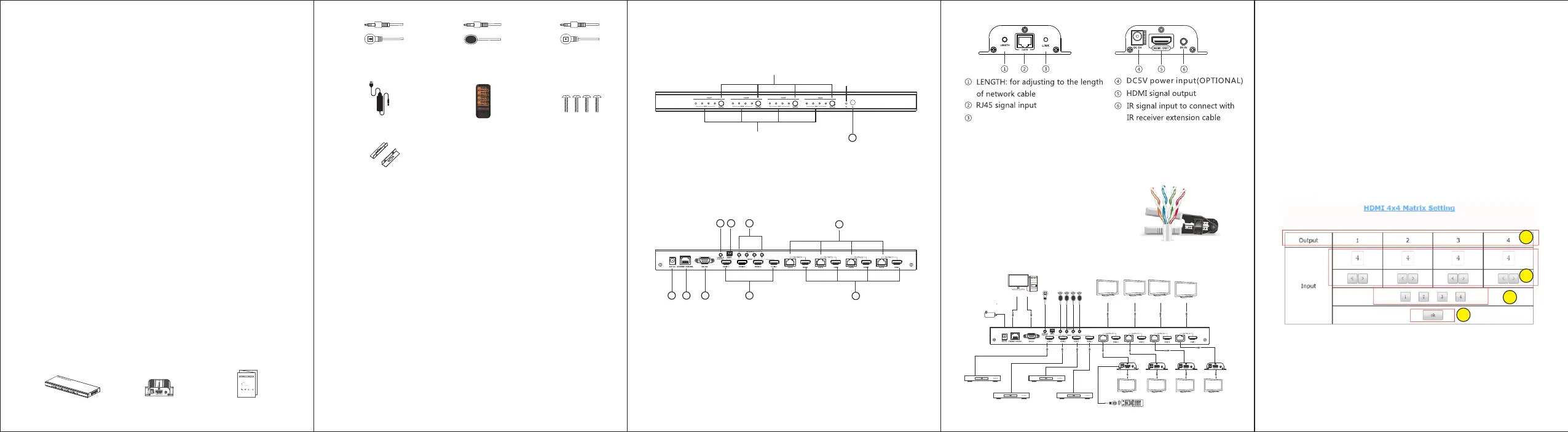
① DC12V Power Input
② Ethernet Control
③ RS232 Serial Port
④ LOCAL CONTROL PORT: Connect
with receiver extension cable,
receive signal from controller
2. Receiver unit (RX)
1. Plug and play
2. Support 20~60KHz IR pass back
3. Support intelligent EDID management
4. Supportresolutionupto1080p@60Hz
5. Transmitter supportsfour HDMI loop-out
6. Transmissiondistanceisupto40metersbyCAT6/6A/7
7. Support to switch and select input source device and output
display by both remote control and button on unit device
8. Support IR remote control, Ethernet control and RS232 control
9. Can be powered by network cable. It only needs to connect the 12V
power supply on the transmitter unit, both transmitter and receivers
start work.
1. HDMI source device (DVD, PS3, Set top box, PC etc)
2. HDMI display device like SDTV, HDTV, and projector with
HDMI port.
3. UTP/STP CAT6/6A/7 cable, follow standard IEEE-568B.
Back Panel
① HDMI input indicator
② Switch: To select HDMI input
③ Power indicator
④ IR Receiving window
123
Remote controller ×1
IR receiver extension
cable ×4
· IMPORTANT SAFETY NOTICE
Please read below safety instructions carefully before installation and
operation:
1. Please pay attention to all the warnings and hints on this device.
2. Do not expose this unit to rain, moisture and liquid.
3. Do not put any stuff into the device.
4. Do not repaire the device or open the enclosure without professional
person guidence to avoid electronic shock.
5. Make sure good ventilation openings to avoid product overheating
damage.
6. Shut off power and make sure environment is safe before installation.
7. Do not plug-in/out the network cables and IR cables when it is in using
to avoid cables damage.
rd
8. UseDC12V/3Aonly. Makesurethespecificationmatchedifusing3
party DCadapters.
Receiver
RJ45output
HDMI input
HDMI source
HDMI output
HDMI local
output
HDMI display
HDMI Matrix Switch
Power
PC
⑤ EDID
⑥ IR outputs for IR Blasters
⑦ HDMI Inputs
⑧ HDMI local outputs
⑨ RJ45 signal output
· FEATURES
· INSTALLATION REQUIREMENT
This product is a 4×4 HDMI Matrix Switch over network cable, with
4 HDMI inputs, 4 RJ45 output and 4 HDMI loop-out. 4 HDMI outputs
send the high definition audio/video signals to 4 HDTV displays at
local site, and at the same time, 4 RJ45 outputs transmit and extend
the audio/video signals to 4 HDTV displays in 40 meters far away via
4 receivers. RS232control, Ethernet control, button control and remote
control make switching/ setting the input and output easily. This
product is perfect for security system, digital monitoring system,
school education system, exhibition center, multimedia conference,
command system etc.
•PRODUCT INTRODUCTION
· PACKAGE CONTENTS
7
8
4
4
56
9
DC12V/3APower x1
IR blaster extension
cable x4
IR receiver extension cable
(LOCAL CONTROL port)×1
5- White/Blue 6- Green
7- White/Brown 8- Brown
2. Connection
•INSTALLATION PROCEDURES
1. How to make a CAT6/6A/7 network cable
Follow the stanard of IEEE-568B:
1- White/Orange 2- Orange
3- White/Green 4- Blue
1 unit (TX). Matrix Transmitter
· PANEL DESCRIPTION
③
FrontPanel
1) Connect HDMI source devices to the transmitter(matrix) inputs via
HDMI cables.
2) If using the HDMI loop-output, connect the HD display devices to
the outputs on the transmitter(matrix) via HDMI cables.
3) Connect the receiver units to the transmitter(matrix) via network
cable, and connect the HD display devices to the HDMI outputs
of the receiver units
4) If using the IR function, connect the IR blaster to the IR OUT on the
transmitter(matrix), and the IR receiver cable to IR IN on the receiver.
5 )Plug the power supply into the Matrix power socket and plug the
power adaptor into a mains socket.
Connection instruction
3. PC Control
The Ehternet RJ45 port is the link for TCP/IP controls, connect to an active
ethernet link with an RJ45 terninater cable.
① The Outputs (TV side) are fixed and cannot be changed.
② Change the Input to display that onto the specified Output TV.
③ These buttons will force the chosen HDMI Input onto all Output TVs.
④ Press OK to confirm.
①
②
HDMI Matrix x1HDMI Receivers x4
User Manual x1
HDMI source
1
2
3
4
Login in IP 192.168.1.200 in a browser (If you can not open the file in
a browser, please keep try in other browser), then will enter above
interface.
Wall-mount kit ×2pcs
Screws ×6pcs
HDMI source
HDMI source
RJ45 indicator led keeps on with
HDMI signal transmission flashes
with no signal transmission
Specyfikacje produktu
| Marka: | Epcom |
| Kategoria: | przedłużacz AV |
| Model: | TT744 |
Potrzebujesz pomocy?
Jeśli potrzebujesz pomocy z Epcom TT744, zadaj pytanie poniżej, a inni użytkownicy Ci odpowiedzą
Instrukcje przedłużacz AV Epcom

30 Września 2024
30 Września 2024
30 Września 2024
30 Września 2024
30 Września 2024
30 Września 2024
30 Września 2024
30 Września 2024
Instrukcje przedłużacz AV
Najnowsze instrukcje dla przedłużacz AV
8 Kwietnia 2025
1 Kwietnia 2025
1 Kwietnia 2025
1 Kwietnia 2025
1 Kwietnia 2025
1 Kwietnia 2025
26 Lutego 2025
20 Lutego 2025
20 Lutego 2025
7 Lutego 2025