Instrukcja obsługi Festo PAML-CP-186-HP3-G112
Festo Niesklasyfikowane PAML-CP-186-HP3-G112
Przeczytaj poniżej 📖 instrukcję obsługi w języku polskim dla Festo PAML-CP-186-HP3-G112 (2 stron) w kategorii Niesklasyfikowane. Ta instrukcja była pomocna dla 15 osób i została oceniona przez 2 użytkowników na średnio 4.7 gwiazdek
Strona 1/2
PAML-CP/-MK-186
Sub-base/Module connector
Festo SE & Co. KG
Ruiter Straße 82
73734 Esslingen
Deutschland
+49 711 347-0
www.festo.com
Assembly instructions
8161951
2021-10b
[8161953]
Translation of the original instructions
© 2021 all rights reserved to Festo SE & Co. KG
1
Applicable documents
All available documents for the product
è
www.festo.com/sp.
2Safety
2.1Safety instructions
–
Only use the product in its original condition without unauthorised modifica-
tions.
–
Only use the product if it is in perfect technical condition.
–
Take the weight of an individual device or a service unit into account.
Dependent on the design, a mounted service unit can weigh more than 100 kg.
–
Under intended use the surface temperature may reach 60 °C. Allow the device
to cool down before working on it.
–Make sure the mounting surface is sufficiently strong for the maximum forces.
–
Only use suitable mounting components.
–Mount the individual device or the service unit only on flat surfaces.
2.2Intended use
–The sub-base PAML-CP serves as an adapter for the pneumatic connection and
for pipe mounting for in-line installation of service units.
–The module connector PAML-MK is used to connect two service units of the
same size.
2.3Training of qualified personnel
Work on the product may only be carried out by qualified personnel who can eval-
uate the work and detect dangers. Personnel must have the relevant mechanical
training.
3Additional Information
–
Accessories
è
www.festo.com/catalogue.
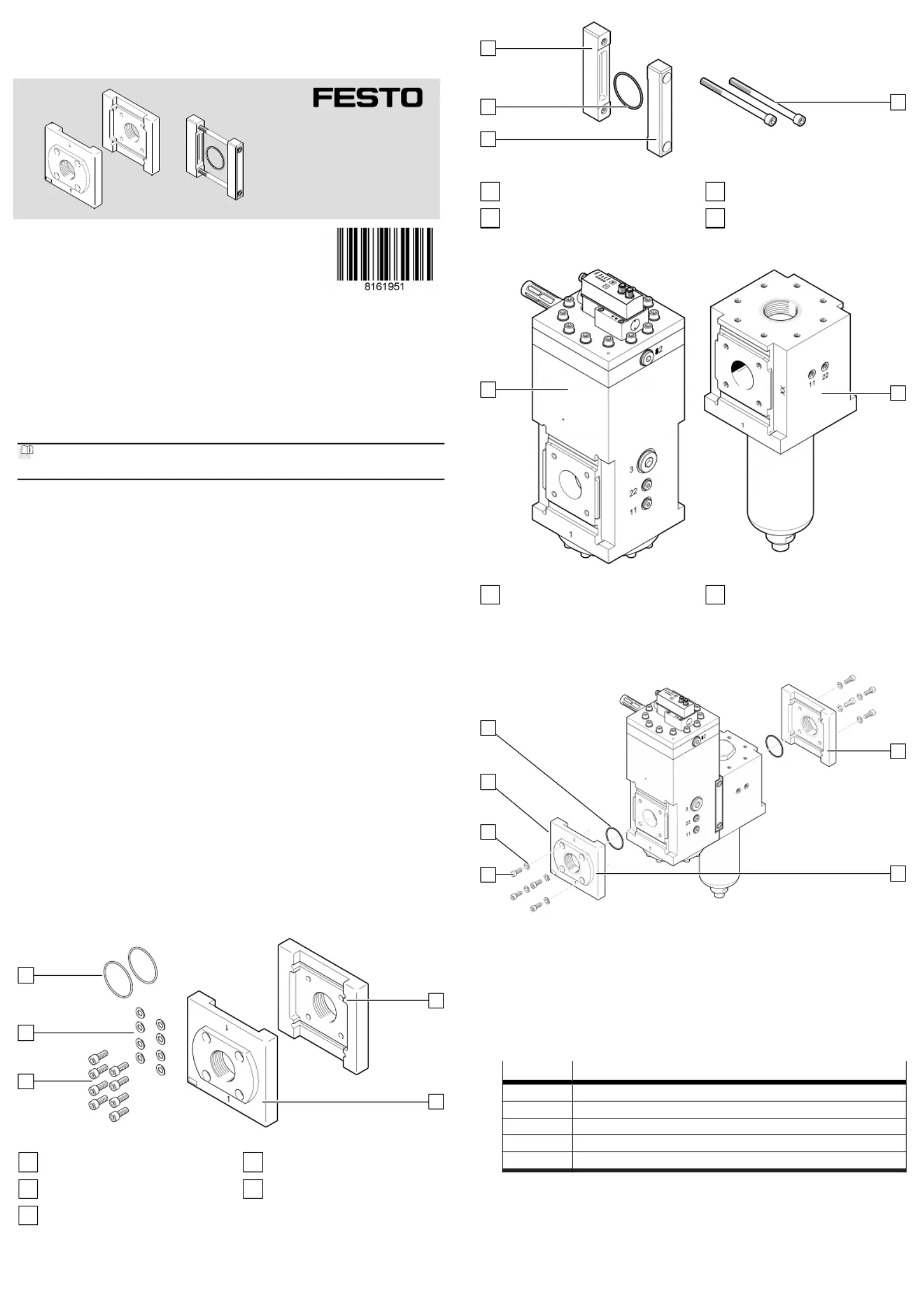
4Product Range Overview
4.1Scope of delivery
1
2
3
4
5
Fig. 1:
Sub-base PAML-CP
1
Front plate (1x)
2
Rear plate (1x)
3
Screw (8x)
4
Washer (8x)
5
O-ring (2x)
6
7
8
9
Fig. 2:
Module connector PAML-MK
6
Screw (2x)
7
Front plate (1x)
8
O-ring (1x)
9
Rear plate (1x)
4.2
Not in scope of delivery
10
11
Fig.3
10
Electrical pressure regulator (1x)
PREL-186
11
Micro filter (1x)
PFML-186
5
Assembly
5.1Mounting the connecting plates PAML-CP
1
2
3
4
5
12
Fig.4
1.Orient the front plate and the rear plate so the stamp number on the12
sub-base corresponds with the stamp number on the housing (1 to 1 and 2 to
2) and the mounting thread for wall mounting points to the rear.aB
2.Insert the O-rings in the slots provided.5
3.
Position the front plate and the rear plate .12
4.Fasten the front plate and the rear plate to the service unit using four12
screws and four washers . Tightening torque: 27 Nm ± 15% 34
5.Comply with the maximum screw-in depth for the pipe connection.
ISO 228Max. screw-in depth [mm]
G1/212
G1 1/420
G1 1/222
G224
G2 1/226
Specyfikacje produktu
| Marka: | Festo |
| Kategoria: | Niesklasyfikowane |
| Model: | PAML-CP-186-HP3-G112 |
Potrzebujesz pomocy?
Jeśli potrzebujesz pomocy z Festo PAML-CP-186-HP3-G112, zadaj pytanie poniżej, a inni użytkownicy Ci odpowiedzą
Instrukcje Niesklasyfikowane Festo

10 Stycznia 2025
10 Stycznia 2025
7 Stycznia 2025
7 Stycznia 2025
7 Stycznia 2025
7 Stycznia 2025
7 Stycznia 2025
7 Stycznia 2025
7 Stycznia 2025
7 Stycznia 2025
Instrukcje Niesklasyfikowane
Najnowsze instrukcje dla Niesklasyfikowane
29 Stycznia 2025
29 Stycznia 2025
29 Stycznia 2025
29 Stycznia 2025
29 Stycznia 2025
29 Stycznia 2025
29 Stycznia 2025
29 Stycznia 2025
29 Stycznia 2025
29 Stycznia 2025