Instrukcja obsługi Gewiss GW90737
Gewiss Niesklasyfikowane GW90737
Przeczytaj poniżej 📖 instrukcję obsługi w języku polskim dla Gewiss GW90737 (2 stron) w kategorii Niesklasyfikowane. Ta instrukcja była pomocna dla 26 osób i została oceniona przez 2 użytkowników na średnio 4.2 gwiazdek
Strona 1/2
%)
L’attuatore con azionamento manuale GW 90 737 serve ad accendere lampade
ed altre utenze tramite contatti NA. Il dispositivo è dotato di otto canali
indipendenti (da A a H) con relé in uscita e un accoppiatore Bus integrato. La
funzione dei canali è determinata dal software caricato dell’utente.
4.5.6<2-2>2;=*42BB*B276../=6B276*5.6<7
1 LED verde: il LED di funzionamento si accende quando
l’applicazione è stata caricata correttamente.
1 LED rosso: controllo programmazione
pulsante 1:programmazione
8 interruttori manuali:per la messa in funzione in manuale dei contatti di
commutazione (da A a H), anche in mancanza della
tensione del Bus.
#$)
$$) I dispositivi adiacenti possono venire danneggiati!
Installare in prossimità dell’attuatore soltanto dispositivi dotati
almeno di isolamento pincipale.
Posizionare il dispositivo sulla guida DIN dal basso e spingere verso
l’alto. Poi spingere la parte alta del dispositivo contro la guida e
agganciarla. Non è richiesta alcuna guida dati.
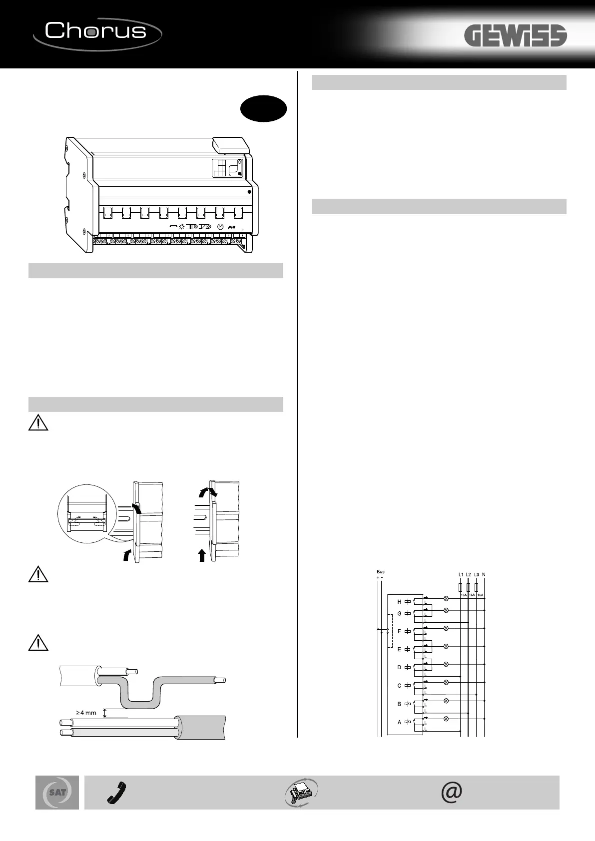
$$) L’attuatore può venire danneggiato. Proteggere i
contatti con interruttori magnetotermici a monte da16 A.
Collegare il dispositivo come mostrato nell’esempio. I cavi sono collegati alle
utenze e alle reti di alimentazione (L1, L2 o L3) tramite morsetti a vite per un
massimo di 16 A. Ogni coppia di collegamenti L è connessa internamente.
Inserire il morsetto di alimentazione Bus e coperchio del cavo.
$$) Si deve assicurare una distanza di sicurezza come in
figura. Assicurarsi che ci sia una distanza di almeno 4 mm tra i
singoli cavi della linea 230 V e la linea del Bus.
&&$ #! #$&
Dopo aver realizzato i collegamenti del dispositivo, viene assegnato
l’indirizzo fisico e impostati i parametri:
Collegare l’interfaccia al Bus
Dare tensione al Bus
Premere il tasto di programmazione (il LED rosso si accende)
Caricamento dell’indirizzo fisico dall’ETS tramite interfaccia (il LED rosso
si spegne)
Caricamento nel dispositivo dei parametri preparati tramite interfaccia (il
LED verde si accende)
Verifica funzione scelta quando il dispositivo è operativo (possibile anche
con l’ausilio dell’ETS)
$$
$.6;276.*=;242*:2*.;<.:6*nessuna
425.6<*B276.-*4=;CC 24 V / circa 15 mA
$.6;276.-22;74*5.6<7CA 4 kV tra Bus e 230 V AC
$$$8 x contatti NA
!:7<.B276.Proteggere i contatti con interruttore magnetotermico a monte
da 16 A.
$.6;276.67526*4.AC 230 V, da 50 a 60 Hz
7::.6<.67526*4.16 A, cos ϕ= 0,6
*:2,7,744.0*<7
-Lampade ad incandescenza: CA 230 V, max. 3600 W con 10.000 cicli di
accensione
-Lampade alogene: CA 230 V, max. 2500 W con 10.000 cicli di accensione
-Lampade fluorescenti: CA 230 V, max 2500 VA, compensate in
parallelo, con 5.000 cicli di accensione
-Carico capacitivo: CA 230 V, 16 A max. 200 µF con 5.000 cicli di accensione
*:2,7526257≥ 24 V CC, 100 mA
:.9=.6B*-2*,,.6;276.max. 10 al minuto a carico nominale
$.58.:*<=:**5+2.6<.
- Funzionamento: da -5°C a +45°C
- Immagazzinamento: da -25°C a +55°C
- Trasporto: da -25°C a +70°C
5+2.6<.,2:,7;<*6<.L’apparecchio è progettato per un uso a un’altitudine
massima di 2000 m. sul livello del mare.
:*-75*;;257-2=52-2<C93%, in assenza di condensazione di umidità
4.5.6<2-2,76<:7447Tasto di programmazione, otto interruttori per la
messa in funzione manuale
4.5.6<2-2>2;=*42BB*B276.
- Controllo programmazione: 1 LED rosso
-Pronto per il funzionamento: 1 LED verde
744.0*5.6<2
- Bus: tramite due spinotti da 1 mm per morsetto di alimentazione Bus
-Conduttore esterno: sette morsetti a vite a 3 moduli (A – G) e un
morsetto a vite a 2 moduli (H) per max. 2,5 mm
2
*:01.BB**88*:.,,127circa. 144mm, 8 moduli EN 50022
26..0=2-*conforme alle linee guida sulla bassa tensione 73/23/EWG,
conforme alle linee guida CEM 89/336/CEE
;.5827-2,766.;;276.
$"%#$&
G
O
FF
H
O
FF
RUN
O
FF
O
FF
O
FF
O
FF
O
FF
FEDCBA
B
L
T
+
--
O
N
Bus
Prog.
1
000W
A
C 230V
16AX
L
L
LL
L
L
L
L
L
L
L
L
L
L
Articolo n.
'
230V
Bus
I
+39 035 946 111
8.30 - 12.30 / 14.00 - 18.00
lunedì ÷ venerdì - monday ÷ friday
+39 035 946 260
sat@gewiss.com
www.gewiss.com
24h
Ai sensi dell’articolo 9 comma 2 della Direttiva Europea 2004/108/CE e dell’articolo R2 comma 6 della Decisione 768/2008/CE si informa che responsabile dell’immissione del prodotto sul mercato Comunitario è:
According to article 9 paragraph 2 of the European Directive 2004/108/EC and to article R2 paragraph 6 of the Decision 768/2008/EC, the responsible for placing the apparatus on the Community market is:
'###8&2*&74<*.6*<.#7<<7<*4A$.4*@5*249=*42<A5*:3;0.?2;;,75
Specyfikacje produktu
| Marka: | Gewiss |
| Kategoria: | Niesklasyfikowane |
| Model: | GW90737 |
Potrzebujesz pomocy?
Jeśli potrzebujesz pomocy z Gewiss GW90737, zadaj pytanie poniżej, a inni użytkownicy Ci odpowiedzą
Instrukcje Niesklasyfikowane Gewiss

1 Października 2024
1 Października 2024
1 Października 2024
1 Października 2024
1 Października 2024
1 Października 2024
1 Października 2024
1 Października 2024
1 Października 2024
1 Października 2024
Instrukcje Niesklasyfikowane
Najnowsze instrukcje dla Niesklasyfikowane
29 Stycznia 2025
29 Stycznia 2025
29 Stycznia 2025
29 Stycznia 2025
29 Stycznia 2025
29 Stycznia 2025
29 Stycznia 2025
29 Stycznia 2025
29 Stycznia 2025
29 Stycznia 2025