Instrukcja obsługi Grunkel SP-15 IN-1
Grunkel nieskategoryzowany SP-15 IN-1
Przeczytaj poniżej 📖 instrukcję obsługi w języku polskim dla Grunkel SP-15 IN-1 (2 stron) w kategorii nieskategoryzowany. Ta instrukcja była pomocna dla 35 osób i została oceniona przez 6 użytkowników na średnio 4.4 gwiazdek
Strona 1/2
SP-15IN1
Soporte jo para televisores
Manual de instrucciones
Instruction manual
ES
EN
PTManual de instruções
GRACIAS POR ESCOGER ESTE PRODUCTO GRUNKEL
GRUNKEL pone a su disposición productos innovadores, duraderos y prácticos. Bajo
un uso responsable y con el mantenimiento adecuado, le proporcionará una larga
vida útil y contribuirá a hacer del día a día una tarea mucho más sencilla.
Agradecemos su conanza y esperamos que disfrute de él.
Descubra el resto de nuestra gama en www.grunkel.com
Este manual es el reproducción en cuanto a características, funcionamiento y estética del producto que usted ha
adquirido salvo error tipográco, de imprenta o traducción. La especicación, funcionamiento y características de
este aparato están sujetos a cambios sin previo aviso.
Este manual é el reprodução em termos de características, operação e estética do produto que você adquiriu,
exceto erro tipográco, impressão ou tradução. A especicação, operação e características deste dispositivo estão
sujeitas a alterações sem aviso prévio.
This instruction manual is an accurate reproduction of the specications, operation and look of the product you
have just bought, except for typographical, print or translation errors. The specications, operation and features of
this product are subject to change without further notice.
•Por favor, lea detenidamente las instrucciones de uso de este
manual al completo antes de ponerlo en funcionamiento.
•Preste especial atención a las indicaciones de seguridad.
•Conserve este manual de instrucciones. Si cede el dispositivo a un
tercero, estas instrucciones también deben ser entregadas
•Guarde también la garantía, el ticket o factura de compra y, si es
posible, la caja con el embalaje interior para posibles solicitudes
en el futuro.
ANTES DE PONER EL PRODUCTO
EN FUNCIONAMIENTO
Tamaño de pantalla: 37” a 65”
Carga máxima: 45kg
VESA: 600 x 400mm máx.
Rango de inclinación: 3° arriba /
10° abajo
Perl: 4,5cm
Soporte de pared (x1)
Brazo de montaje (x2)
Manual de instrucciones (x1)
Kit de herramientas (x1)
Lea detenidamente estas instrucciones antes de comenzar. Si no está seguro de alguna
parte del proceso, contacte con un profesional o instalador para ayuda. Una instalación
inadecuada puede derivar en accidentes o lesiones.
La pared o la supercie donde vaya a instalarse el soporte debe soportar el peso combi-
nado del soporte y el televisor. En caso contrario, debe ser reforzada.
EspecicacionesContenido
Medidas de seguridad
LOS DATOS SOBRE CARGA MÁXIMA Y TAMAÑO MÁXIMO ADMITIDOS DE
ESTE SOPORTE DEPENDEN DE CADA MODELO DE TELEVISOR. LA VERACI-
DAD Y SEGURIDAD DE LOS DATOS PROPORCIONADOS POR CADA TELEVI-
SOR SON RESPONSABILIDAD DE SUS RESPECTIVOS FABRICANTES, Y NO
ESTÁN VINCULADAS A LAS ESPECIFICACIONES DE ESTE SOPORTE.
¡ATENCIÓN!
Parte 1A – Montaje en pared (yeso o escayola)
¡IMPORTANTE! Por motivos de seguridad, este soporte debe asegurarse con al menos
dos vigas de madera capaces de soportar el peso combinado del soporte y la pantalla.
Escoja una pared lisa y con suciente grosor. Use un localizador de vigas para localizar
dos vigas adyacentes donde desee instalar su soporte. Marque los dos bordes de am-
bas vigas para identicar el centro exacto.
NOTA: Debe usar el centro de cada viga para evitar agrietamiento o rotura de la madera
durante la instalación.
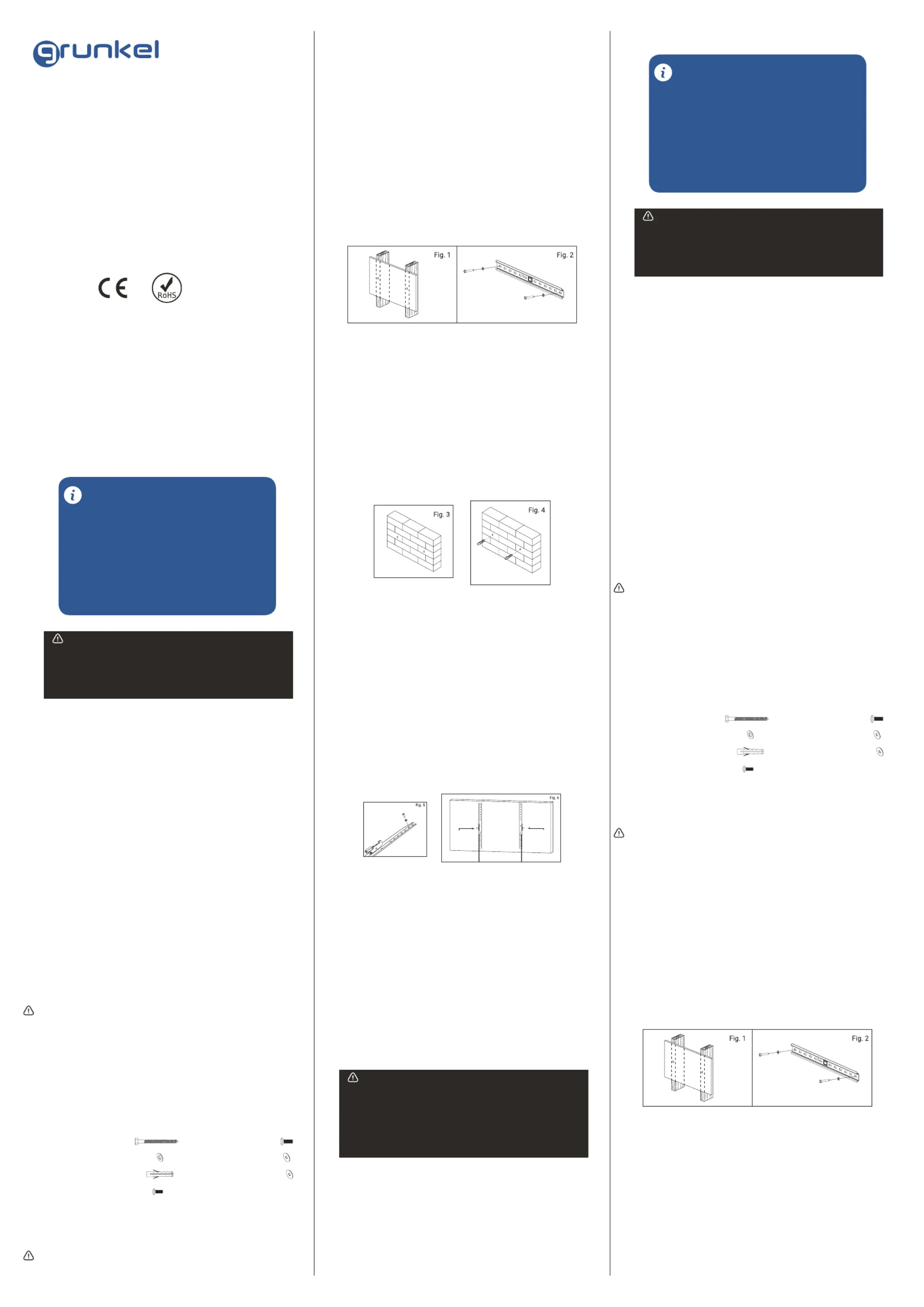
Coloque la parte posterior del soporte contra la pared. Asegúrese de que esté nivelado
usando la burbuja del nivel integrado.
Mientras otra persona sostiene el soporte en posición, marque dos puntos (uno por
cada viga) para asegurar el soporte a la pared (ver Fig. 1).
Perfore un agujero de 6 mm (1/4“) en las dos marcas realizadas como guía.
Coloque el soporte contra la pared y fíjelo usando los tornillos (A) y arandelas (B) pro-
vistos (ver Fig. 2). No los apriete en exceso y no suelte el soporte hasta que todos los
tornillos estén colocados. Asegúrese de que el soporte permanece nivelado después
de que los tornillos se hayan apretado.
Use a high quality stud nder to locate two adjacent studs where you wish to install your
mount. Mark both edges of each stud to help identify the exact center.
NOTE: You must use the center of the stud to avoid cracking or splitting the wood during
installation.
Place the wall plate against the wall with the arrow pointing up and level it using the
integrated bubble level.
While another person holds the wall plate in position, mark two locations (one per stud)
for securing the mount to the wall (see Fig. 1).
Set the wall plate aside and drill a 6 mm (1/4”) pilot hole at each marked location.
Place the wall plate back against the wall and attach it using the lag bolts (A) and lag
bolt washers (B) provided (see Fig. 2). Do not over-tighten these bolts and do not relea-
se the wall plate until all bolts are in place. Ensure that the wall plate remains level after
all bolts are secured.
Parte 1A – Montaje en pared (hormigón)
¡IMPORTANTE! Por motivos de seguridad, el muro debe ser capaz de soportar el peso
combinado del soporte y la pantalla. El fabricante no asume responsabilidad por fallo
producido por muros de fuerza insuciente.
Coloque la parte posterior del soporte contra la pared. Asegúrese de que esté nivelado
usando la burbuja del nivel integrado.
Mientras otra persona sostiene el soporte en su lugar, marque dos ubicaciones en la
pared para asegurar el soporte (ver g. 3).
Coloque el soporte a un lado y perfore un agujero de 10 mm (3/8”) en cada ubicación
marcada. Retire cualquier exceso de polvo de los agujeros.
Inserte un espiche en cada agujero de modo que quede a ras de la supercie de cemen-
to (ver Fig. 4). Puede usarse un martillo para golpear los espiches ligeramente hasta
que queden en su sitio.
Parte 1B – Mounting to the Wall (Concrete)
IMPORTANT! For safety reasons, the concrete wall must be capable of supporting the
combined weight of the mount and the display. The manufacturer takes no responsibi-
lity for failure caused by walls of insufcient strength.
Place the wall plate against the wall in the desired location with the arrow pointing up
and level it using the integrated bubble level.
While another person holds the wall plate in place, mark two locations on the wall for
securing the mount (see Fig. 3).
Set the wall plate aside and drill a 10 mm (3/8”) hole at each marked location. Remove
any excess dust from the holes.
Insert a concrete anchor (C) into each hole so that it is ush with the concrete surface
(see Fig. 4). A hammer can be used to lightly tap the anchors into place if necessary.
Parte 2 – Ensamblar el soporte al televisor
¡IMPORTANTE! Tenga especial cuidado durante esta parte de la instalación. Si es posi-
ble, evite colocar su pantalla hacia abajo p1-ya que podría dañar la supercie.
NOTA: este soporte incluye una selección de tornillos de diferentes diámetros y longi-
tudes para ajustarse a una amplia variedad de modelos de televisor. No todo el mate-
rial en el kit será usado. Si no puede encontrar el tornillo del tamaño adecuado en el kit,
consulte a su proveedor para obtener más información.
Determine el diámetro de tornillo correcto probando cuidadosamente un tornillo de
cada tamaño (M6 y M8) del material provisto (ver Fig. 5). No fuerce ninguno de los
tornillos, si nota resistencia pare de inmediato y pruebe con un tornillo más pequeño.
Fije los brazos de montaje en la parte de atrás de su televisor usando los tornillos iden-
ticados en el paso anterior. Si está usando tornillos M6 deberá usar las arandelas M6
(F). Si está usando los tornillos M8 deberá usar las arandelas M8 (G).
NOTA: Los brazos de montaje tienen que estar sujetos con los tornillos de ajuste de in-
clinación mirando hacia las partes exteriores (lejos del centro de la pantalla) (ver Fig.6).
Si no, la función de la inclinación no podrá llevarse a cabo.
Parte 3 – Ensamblaje nal
Aoje ambos tornillos de ajuste de inclinación y establezca el ángulo deseado. Asegú-
rese de que ambos brazos del soporte están colocados en el mismo ángulo antes de
apretar y asegurar de nuevo ambos tornillos.
Con la ayuda de otra persona, levante cuidadosamente su televisor y colóquelo en el
soporte de pared. Presione suavemente sobre la parte de abajo de su televisor para que
los clips en los brazos del soporte se bloqueen en el soporte de pared. No suelte el tele-
visor hasta que los brazos del soporte estén enganchados con seguridad en el soporte.
¡IMPORTANTE! Los tornillos de seguridad tienen que estar apretados en todo momento
para prevenir que la pantalla caiga del soporte accidentalmente.
Limpie el soporte periódicamente con un paño seco. Inspeccione todos los tornillos
y partes en intervalos frecuentes para asegurarse de que ninguna conexión se hayan
aojado con el tiempo. Vuelva a apretar si es necesario.
Para retirar su televisor de la pared, tire de ambos cables para desbloquear los brazos
del soporte y levante el televisor cuidadosamente del soporte de pared.
Localice tuberías, cables o cualquier otro peligro en la pared donde desee instalar el
soporte antes de taladrar.
Debe utilizarse equipamiento de seguridad y herramientas apropiadas. En caso contra-
rio podrían producirse accidentes o lesiones.
Se recomienda que la instalación sea llevada a cabo por dos personas. No intente le-
vantar una pantalla pesada sin ayuda.
Siga las instrucciones y recomendaciones referentes a la ventilación adecuada y ubi-
caciones apropiadas para montar su televisor. Consulte el manual de usuario de su
televisor particular para obtener más información.
PRECAUCIÓN: Este soporte ha sido diseñado para uso solo con un peso máximo de
45kg. Su uso con peso superior al indicado puede resultar en inestabilidad causando
posibles lesiones.
Destornillador
Carraca con cuenca de 13 mm
(1/2”)
Taladro eléctrico o portátil
Broca de 6 mm (1/4”) para instalación
en pared de yeso o escayola
Broca de 10 mm (3/8”) para instalación
(A) Tornillo M8 x 63
(B) Arandela (x2)
(E) Tornillo M8 x 12 (x4)
(C) Espiche (x2)
(F) Arandela M6 (x4)
(G) Arandela M8 (x4)
(D) Tornillo M6 x 12 (x4)
Parte 1A – Montaje en pared (yeso o escayola)
¡IMPORTANTE! Por motivos de seguridad, este soporte debe asegurarse con al menos
dos vigas de madera capaces de soportar el peso combinado del soporte y la pantalla.
Herramientas requeridas
Material
Instalación
Locate pipes, wires, or any other hazards in the wall where you wish to install the mount
before drilling.
Safety gear and proper tools must be used. Failure to do so can result in injury or da-
mage.
Two people are recommended for installation. Do not attempt to lift a heavy display
without assistance.
Follow all instructions and recommendations regarding adequate ventilation and suita-
ble locations for mounting your display. Consult the owner‘s manual for your particular
display for more information.
CAUTION: This wall mount is intended for use only with the maximum weight of 45 kg
(100 lbs). Use with heavier than the maximum weights indicated may result in instabi-
lity causing possible injury.
Phillips Head Screw Driver
Ratchet or Driver with 13 mm (1/2”) Socket
Electric or Portable Drill
6 mm (1/4”) Drill Bit and Stud Finder for Drywall Installation
10 mm (3/8”) Masonry Bit for Concrete Installation
(A) M8 x 63 Screw (x2)
(B) Lag Bolt Washer (x2)
(E) M8 x 12 Screw (x4)
(C) Concrete Anchor (x2)
(F) M6 Washer (x4)
(G) M8 Washer (x4)
(D) M6 x 12 Screw (x4)
Part 1A – Mounting to the Wall (Drywall)
IMPORTANT! For safety reasons, this mount must be secured to at least two wood
studs no less than 16” apart. The studs must be capable of supporting the combined
weight of the mount and display.
Tools required
Material
Installation
LOS NIÑOS MENORES DE 8 AÑOS NO DEBEN UTILIZAR NI LIMPIAR ESTE
APARATO SIN LA SUPERVISIÓN DE UN ADULTO. TAMPOCO PUEDE SER
UTILIZADO NI LIMPIADO POR PERSONAS CON CAPACIDADES FÍSICAS,
MENTALES O SENSORIALES REDUCIDAS, SIN EXPERIENCIA O CONOCI-
MIENTO DEL USO DEL MISMO, O QUE NO HAYAN RECIBIDO LA FORMA-
CIÓN ADECUADA BAJO LA SUPERVISIÓN DIRECTA DE UNA PERSONA
CAPACITADA.
¡ATENCIÓN!
ENG - Instruction manual
•Please, read carefully the entire instruction manual before using it.
•Pay special attention to the safety indications.
•Keep this instruction manual. If you hand over this applicance to
another person, these instructions must be also be transferred.
•Keep also the guarantee card, purchase ticket or invoice. If
possible, keep the original box with all the accessories included for
future inquiries.
BEFORE PUTTING THE APPLIANCE
INTO OPERATION
Display Size: 37” to 65”
Maximum Load: 45 kg
Mounting Pattern: 600 mm x 400
mm max.
Tilt Range: 3° up to 10° down
Prole: 4,5 cm
Wall Plate (x1)
Mount Arm (x2)
Instruction Manual (x1)
Hardware Kit (x1)
Read these instructions before you begin. If you are unsure of any part of the process,
contact a professional contractor or installer for assistance. Improper installation can
result in injury or damage.
The wall or mounting surface must be capable of supporting the combined weight of
the mount and the display; if not, the structure must be reinforced.
SpecicationsContent
General safety instructions
WARNING!
THE INFORMATION RELATED TO MAXIMUM LOAD AND MAXIMUM SIZE
SUPPORTED BY THIS MOUNT DEPEND ON EACH TV MODEL INDIVIDUALLY.
THE TRUTHFULNESS AND SAFETY OF THE PROVIDED INFORMATION ARE
THE SOLE RESPONSIBILITY OF THEIR RESPECTIVE MANUFACTURERS,
AND ARE NOT ASSOCIATED WITH THIS PRODUCT IN ANY WAY.
Specyfikacje produktu
| Marka: | Grunkel |
| Kategoria: | nieskategoryzowany |
| Model: | SP-15 IN-1 |
| Kolor produktu: | Czarny |
| Waga produktu: | 4820 g |
| Podręcznik użytkownika: | Tak |
| Certyfikat środowiskowy (zrównoważonego rozwoju): | RoHS |
| Certyfikaty: | CE |
| Waga wraz z opakowaniem: | 6090 g |
| Instrukcja szybkiej instalacji: | Tak |
| Liczba obsługiwanych wyświetlaczy: | 1 |
| Waga paczki: | 6.09 kg |
| Interfejs do montażu panelu: | 200 x 200,200 x 400,300 x 300,400 x 400,600 x 400 mm |
| Obracany: | -90 - 90 ° |
| Zakres kąta nachylenia: | -2 - 5 ° |
| Maksymalna waga: | 65 kg |
| Typ mocowania: | Ściana |
| Kąt obrotu: | 180 ° |
| Zestaw do montażu: | Tak |
| Dołączone śruby: | Tak |
| Minimalna wielkość ekranu: | 37 " |
| Maksymalna wielkość ekranu: | 65 " |
| Minimalny uchwyt VESA: | 200 x 200 mm |
| Maksymalny uchwyt VESA: | 600 x 400 mm |
| Wbudowana poziomica: | Tak |
Potrzebujesz pomocy?
Jeśli potrzebujesz pomocy z Grunkel SP-15 IN-1, zadaj pytanie poniżej, a inni użytkownicy Ci odpowiedzą
Instrukcje nieskategoryzowany Grunkel

28 Września 2024
16 Września 2024
27 Maja 2024
Instrukcje nieskategoryzowany
Najnowsze instrukcje dla nieskategoryzowany
28 Października 2024
28 Października 2024
27 Października 2024
27 Października 2024
27 Października 2024
27 Października 2024
27 Października 2024
27 Października 2024
27 Października 2024
27 Października 2024