Instrukcja obsługi Hikvision DS-KV1101-ME2/Flush
Hikvision Niesklasyfikowane DS-KV1101-ME2/Flush
Przeczytaj poniżej 📖 instrukcję obsługi w języku polskim dla Hikvision DS-KV1101-ME2/Flush (4 stron) w kategorii Niesklasyfikowane. Ta instrukcja była pomocna dla 34 osób i została oceniona przez 7 użytkowników na średnio 4.6 gwiazdek
Strona 1/4
DS-KV1101-ME2
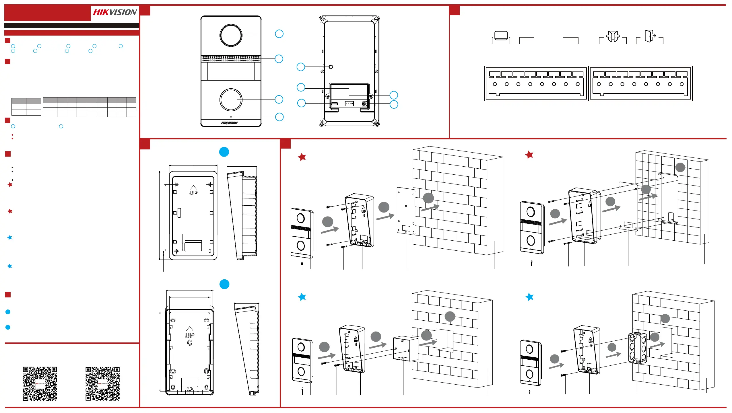
Analog Villa Door StaonUD20935B-B
Camera
2
Call Buon
3
Microphone
4
TAMPER
5
Terminals
6
Debugging Port
7
DIP Switch
8
Note: The debugging port is used for debugging only.
Terminal and Wiring
2
Installaon Accessory
3
ENGLISH
Diagram References
Appearance
1
Flush Mounng with Gang Box (Type I)
1. Cave the installaon hole in the wall.
Note: The suggested dimension of the installaon hole should be larger than the gang box.
2. Insert the gang box to the hole chiseled on the wall.
3. Fix the mounng plate to the gang box with 2 screws.
Note: The dimension of the gang box is 75mm(width) × 75mm(length) × 46mm(depth), thele and
right holes will be applies.
4. Secure the door staon to the mounng plate with the set screw.
Surface Mounng without Gang Box
Make sure all related equipments are power-off during the installaon.
Tools that you need to prepare for installaon:
Drill (ø2.846) and gradienter.
Purchase the protecve shield before installaon.
Before You Start
1. Sck the mounng template on the wall. Drill the screw holes according to the
mounng template. Remove the mounng template from the wall.
2. Align and secure the mounng plate on the wall with 4 supplied screws according to
the screw holes.
3. Install the door staon to the mounng plate. Fix the device on the mounng plate
with the set screw.
11
Local Operaon
5
1
3
2
3
4
5
6
7
8
9
1
Loudspeaker
NC: Door Lock Relay Output (NC)
NO: Door Lock Relay Output (NO)
COM: Common Interface
12 VDC OUT: Power Supply Output
GND: Grounding
Juncon Box
2
1
Mounng Plate
Note:
The dimension of the juncon box is 159.9 mm × 86.7 mm × 53.59 mm.
The dimension of the mounng plate is 142 mm × 82.87 mm × 43.38 mm.
Installaon
4
Note: Video intercom villa door staon supports surface mounng.
2
Wire the door staon to the indoor staon with 2-wire cables.
You can call the resident by pressing the call buon.
Press the call buon of the door staon, all linked indoor staons start ringing.
Note: While one of linked indoor staons receive the call, the others will stop ringing.
Flush Mounng with Juncon Box
1. Cave the installaon hole, and pull the cable out.
Note: The suggest dimension of the installaon hole is
2. Sck the mounng template into to the installaon hole.
3. Insert the juncon box into the hole and fix it with 4 screws according to the screws
holes.
4. Insert the door staon into the juncon box, and fix it with set screw.
Flush Mounng with Gang Box (Type II)
1. Cave the installaon hole in the wall.
Note: The suggested dimension of the installaon hole should be larger than the gang box.
2. Insert the gang box to the hole chiseled on the wall.
3. Fix the mounng plate to the gang box with 2 screws.
Note: The dimension of the gang box is 55mm(width) × 101mm(length) × 38.5mm(depth), theupper
and lower holes will be applies.
4. Secure the door staon to the mounng plate with the set screw.
There are 2 size of the gang boxes adapted to the device.
Size 1: 75 mm(width) 75 mm(length) 46 mm(depth).× ×
Size 2: 55 mm(width) 101 mm(length) 38.5 mm(depth).× ×
DIP Switch
DIP 1 is used to coding the address of door staon. DIP 2, 3,4 are used to coding the unlock
duraon.
LP/LN: For the access of Indoor Staon
Unlock
Duraon(s)
12345678
DIP 2
DIP 3
DIP 4
OFFOFFOFFOFF
OFF
OFF
OFFOFF
OFF
OFF
OFF
OFF
ON
ON
ON
ON
ON
ON
ON
ON
ON
ON
ON
ON
Address
DIP 1
OFF
ON
1
2
1
2
Flush Mounng with Gang Box (Type I)Flush Mounng with Gang Box (Type II)
Surface Mounng without Gang Box
Flush Mounng with Juncon Box
4
1
2
3
1
2
3
4
1
2
3
4
1
2
3
4
Set ScrewDoor StaonScrewsMounng PlateMounng TemplateWall
Set ScrewDoor StaonScrewsMounng PlateMounng TemplateWall
Set ScrewDoor StaonScrewsMounng PlateGang BoxWall
Set ScrewDoor StaonScrewsMounng PlateGang BoxWall
Unit:mm
Unit:mm
43.38
82.87
72.2
142
53.59
86.7
159.91
120
8.78
15
30
AIN1/AIN2/AIN3/AIN4: For the access of Alarm Input Device
Up to 2 door staon can be connected to the system.
Switch the DIP 1 to set the address of the door staon. The address is unique.
1
Unlock Duraon
Switch the DIP 2, 3, 4 to coding the unlock duraon of the door staon. Refers to
the Terminal and Wiring for details.
Note: Unlock duraon ranges from 1 to 8 seconds.
2
Call Resident
NO2
COM2
NC2
NO1
COM1
NC1
GND
12VOUT
LP
LN
AIN4
AIN3
AIN2
AIN1
GND
GND
ALARM IN
Screw for Volume Adjustment
9
Scan the following QR Code to get the
device communicaon matrix.
Note that the matrix contains all communicaon
ports of Hikvision access control and video
intercom devices.
Scan the following QR Code to get the
device common serial port commands.
Note that the command list contains all
commonly used serial ports commands for all
Hikvision access control and video intercom
devices.
Specyfikacje produktu
| Marka: | Hikvision |
| Kategoria: | Niesklasyfikowane |
| Model: | DS-KV1101-ME2/Flush |
Potrzebujesz pomocy?
Jeśli potrzebujesz pomocy z Hikvision DS-KV1101-ME2/Flush, zadaj pytanie poniżej, a inni użytkownicy Ci odpowiedzą
Instrukcje Niesklasyfikowane Hikvision

11 Stycznia 2025
30 Grudnia 2025
8 Grudnia 2024
8 Grudnia 2024
8 Grudnia 2024
8 Grudnia 2024
8 Grudnia 2024
8 Grudnia 2024
8 Grudnia 2024
8 Grudnia 2024
Instrukcje Niesklasyfikowane
Najnowsze instrukcje dla Niesklasyfikowane
29 Stycznia 2025
29 Stycznia 2025
29 Stycznia 2025
29 Stycznia 2025
29 Stycznia 2025
29 Stycznia 2025
29 Stycznia 2025
29 Stycznia 2025
29 Stycznia 2025
29 Stycznia 2025