Instrukcja obsługi Lancom IAP-1781VAW+
Przeczytaj poniżej 📖 instrukcję obsługi w języku polskim dla Lancom IAP-1781VAW+ (2 stron) w kategorii router. Ta instrukcja była pomocna dla 32 osób i została oceniona przez 9 użytkowników na średnio 4.1 gwiazdek
Strona 1/2
LANCOM, LANCOM Systems, LCOS, LANcommunity and Hyper Integration are registered trademarks. All other names or descriptions used may
be trademarks or registered trademarks of their owners. This document contains statements relating to future products and their attributes.
LANCOM Systems reserves the right to change these without notice. No liability for technical errors and/or omissions. 111858/0619
4
Please observe the
following when setting
up the device
ADo not rest any objects
on top of the device
ACAUTION! - Device
surface may be hot
during operation
AThis device complies
with the regulations for
devices of protection
class 2 with functional
ground
LANCOM 1681V
Power
VDSL
Online
ETH 1
VPN
TH 3
ETH 4
Hardware
Power supplyInternal power supply (100-240 V, 50-60 Hz)
Power consumptionMax. ca. 14 W
EnvironmentTemperature range -25–70 °C, humidity 0–95 %, non-condensing
HousingRobust metal housing, protection class IP 54, dimensions 250x158x55 mm (HxWxD)
Number of fansNone; fanless design, no rotating parts, high MTBF
Interfaces
WAN: VDSL2
AVDSL2 as per ITU G.993.2; proles 8a, 8b, 8c, 8d, 12a, 12b, 17a
ACompatible to VDSL2 from Deutsche Telekom AG (only over ISDN)
AADSL conformity according to:
ADSL2+ over ISDN as per ITU G.992.5 Annex B /J with DPBO (POTS: Annex A/Annex M),
ADSL2 over ISDN as per ITU G.992.3 Annex B (POTS: Annex A/L),
ADSL over ISDN as per ITU G.992.1 Annex B (POTS: Annex A)
ASupports just one virtual connection at a time in ATM (VPI-VCI pair)
ETH2 individual ports, 10 / 100 / 1000 Mbps Gigabit Ethernet, by default set to switch mode. 1 port
can be operated as additional WAN ports. Ethernet ports can be electrically disabled in the LCOS
conguration.
ISDNInternal (NT) ISDN S
0
bus
Ant 1, Ant 2Two NJ connectors for external LANCOM AirLancer antennas or for antennas from other vendors.
Please respect the restrictions which apply in your country when setting up an antenna system. For
information about calculating the correct antenna setup, please refer to
www.lancom-systems.com.
WAN protocols
VDSL, ADSL, EthernetPPPoE, PPPoA, IPoA, Multi-PPPoE, ML-PPP, PPTP (PAC or PNS) and IPoE (with or without DHCP),
RIP-1, RIP-2, VLAN, GRE, EoGRE, L2TPv2 (LAC or LNS), IPv6 over PPP (IPv6 and IPv4/IPv6 dual stack
session), IP(v6)oE (autoconguration, DHCPv6 or static)
ISDN1TR6, DSS1 (Euro-ISDN), PPP, X75, HDLC, ML-PPP, V.110/GSM/HSCSD
Declaration of Conformity
Hereby, LANCOM Systems declares that this radio equipment is in compliance with Directive 2014/53/EU. The full text of the
EU declaration of conformity is available at the following internet address: www.lancom-systems.com/ce/
Package contents
DocumentationQuick Reference Guide (DE/EN), Installation Guide (DE/EN)
Cables1 Ethernet cable, 3m; 1 DSL cable, 3 m; ISDN cable, 3m; 1 power cord, 3m
Accessories1 wall mount kit, 1 reset magnet
This product contains separate open-source software components which are subject to their own licenses, in particular the
General Public License (GPL). The license information for the device rmware (LCOS) is available on the device‘s WEBcong
interface under “Extras > License information“. If the respective license demands, the source les for the corresponding
software components will be made available on a download server upon request.
gPower
OffDevice switched off
Green, permanently*Device operational,
resp. device paired / claimed and LANCOM
Management Cloud (LMC) accessible
Green / orange, blinkingConguration password not set. Without a
conguration password, the conguration
data in the device is unprotected.
Red, blinkingCharge or time limit reached
1x green inverse
blinking*
Connection to the LMC active, pairing OK,
device not claimed
2x green inverse
blinking*
Pairing error, resp.
LMC activation code not available
3x green inverse
blinking*
LMC not accessible, resp.
communication error
fVPN
OffVPN connection not active
Green, permanentlyVPN connection active
Green, ashingVPN connection establishment
aETH1 / ETH2
OffNo network device connected
Green, permanentlyNetwork device connected, no data trafc
Green, ickeringData transmission
dISDN
OffInterface disabled
Green, permanentlyD-channel active
Orange, permanentlyB-channel active
Green, blinkingISDN connection active
Orange, blinkingISDN connection establishment
Red / orange, blinkingISDN hardware error
eVoIP
OffNo SIP accounts dened or VCM disabled
Green, permanently All dened and active SIP accounts
(outgoing) have been successfully
registered
Red, permanentlyNot all dened and active SIP accounts
have been registered
(possibly still in process)
Red or green,
inversely ashing
Number of currently used lines
(connecting or connected)
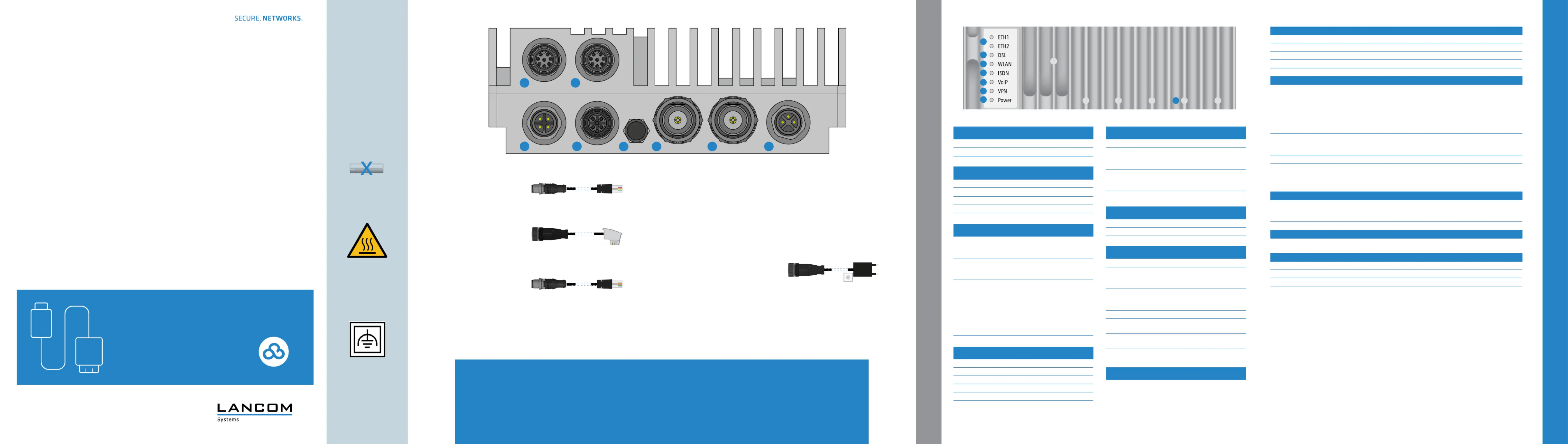
SETTING UP AND CONNECTING THE DEVICE
TECHNICAL DATA
c WLAN
OffNo Wi-Fi network dened or Wi-Fi module
deactivated. The Wi-Fi module is not
transmitting beacons.
Green, permanentlyAt least one Wi-Fi network is dened and
Wi-Fi module activated. The Wi-Fi module
is transmitting beacons.
Green, inverse ashingNumber of ashes = number of connected
Wi-Fi stations and P2P wireless connec-
tions, followed by a pause (default).
Alternatively the frequency of the ashing
can indicate signal strength over the
dened P2P link or the signal strength
between the access point and the device
operating in client mode.
Green, blinkingDFS scanning or other scan procedure
LANCOM IAP-1781VAW+
Quick Reference Guide
Cudeadylo-r
a
b
Ethernet interface
Connect the interfaces (ETH 1) or a
(ETH 2) with the included network b
cable to your PC or a LAN switch.
c
VDSL- / ADSL interface
Use the supplied DSL cable for the
IP-based line to connect the VDSL
interface and the provider’s telephone
socket. (For more information, please
contact your Internet service provider.)
d
ISDN interface
Connect the internal (NT) ISDN bus
with the included cable to an ISDN
phone or an ISDN phone system.
e
Membrane seal
Only to be opened by a service technician
f
g
Wi-Fi antennas
Connect the Wi-Fi antennas (not included) to
the N connectors Ant 1 and Ant 2. e f
Depending on how the antennas are to be
used, ‘Antenna Grouping’ may need to be
congured in order to provide the desired
MIMO behavior.
h
Power
Supply power to the device via the power
connector.
*) The additional power LED statuses are displayed in 5-seconds
rotation if the device is congured to be managed by the LANCOM
Management Cloud.
The device is designed for protection category IP54 and thus protected all-around against splash water and dust in harmful quantity.
The device has to be installed in sufciently protected environment, so that no direct weathering can occur.
When working with separately purchased antennas, please ensure you do not exceed the maximum permissible transmission power. The system operator is
responsible for adhering to the threshold values.
Antennas are only to be attached or changed when the device is switched off. Mounting or demounting antennas with the device switched on may cause the
destruction of the Wi-Fi module!
5
Before initial startup, please make sure to take notice of the information regarding the intended use in the enclosed installation guide!
a
b
b
c
d
e
f
g
h
a
c
d
fgh
e
hReset
Reset areaOperation via the enclosed magnet unit.
The imprint shows the correct insertion
position between the cooling ribs.
short insertion: device restart
long insertion: device reset
b DSL
OffInterface disabled
Green, permanentlyDSL connection active
Green, ickeringDSL data transmission
Red, ickeringDSL transmission error
Red / orange, blinkingDSL hardware error
Specyfikacje produktu
| Marka: | Lancom |
| Kategoria: | router |
| Model: | IAP-1781VAW+ |
Potrzebujesz pomocy?
Jeśli potrzebujesz pomocy z Lancom IAP-1781VAW+, zadaj pytanie poniżej, a inni użytkownicy Ci odpowiedzą
Instrukcje router Lancom

9 Marca 2025
3 Stycznia 2025
3 Stycznia 2025
3 Stycznia 2025
5 Grudnia 2024
5 Grudnia 2024
5 Grudnia 2024
2 Października 2024
2 Października 2024
2 Października 2024
Instrukcje router
Najnowsze instrukcje dla router
9 Kwietnia 2025
9 Kwietnia 2025
8 Kwietnia 2025
3 Kwietnia 2025
2 Kwietnia 2025
1 Kwietnia 2025
30 Marca 2025
30 Marca 2025
30 Marca 2025
30 Marca 2025