Instrukcja obsługi Microchip MCP73830
Microchip Niesklasyfikowane MCP73830
Przeczytaj poniżej 📖 instrukcję obsługi w języku polskim dla Microchip MCP73830 (8 stron) w kategorii Niesklasyfikowane. Ta instrukcja była pomocna dla 13 osób i została oceniona przez 9 użytkowników na średnio 4.0 gwiazdek
Strona 1/8
2022
Microchip Technology Inc. and its subsidiaries
DS90003289B-page 1
TB3289
INTRODUCTION
This document describes a Total System Solution
(TSS) for a single-cell Li-Ion/Li-Polymer battery
charger, consisting of a MCP16311/2 synchronous
buck switching regulator, a MCP73830 1A dedicated
battery charger and an external voltage drop
compensation circuit.
The proposed application circuit offers an effective
solution for the fast charging process of Li-Ion/Li-
Polymer batteries from a wide input voltage range of 5V
to 30V.
LI-ION BATTERIES
When choosing the battery for a specific application,
there are several technical aspects that should be
considered:
•Rechargeable Battery vs. Primary
•Rated Capacity vs. Useful Capacity
•Internal Resistance and Pulse Capability
•Temperature Effects and Storage
•Safety and Transportation
The drawbacks of using a poor solution are:
•Reduced Runtime and Low Efficiency
•Uncertain Reliability and Leakage
Li-Ion batteries have gained popularity and are highly
utilized due to their advantages compared to other
chemistries, as follows:
•High-Energy Density
•Low Self-Discharge Current
•Low Maintenance Required
•High-Power Density
•High-Discharge Current Rate
•High-Charging Current Rate
On the other hand, as previously mentioned, there are
also a few downsides related to:
• Aging
•Need for Protection Circuitry to Maintain Voltage
and Current within Safe Limits
•Manufacturing Costs
•Transportation Conditions
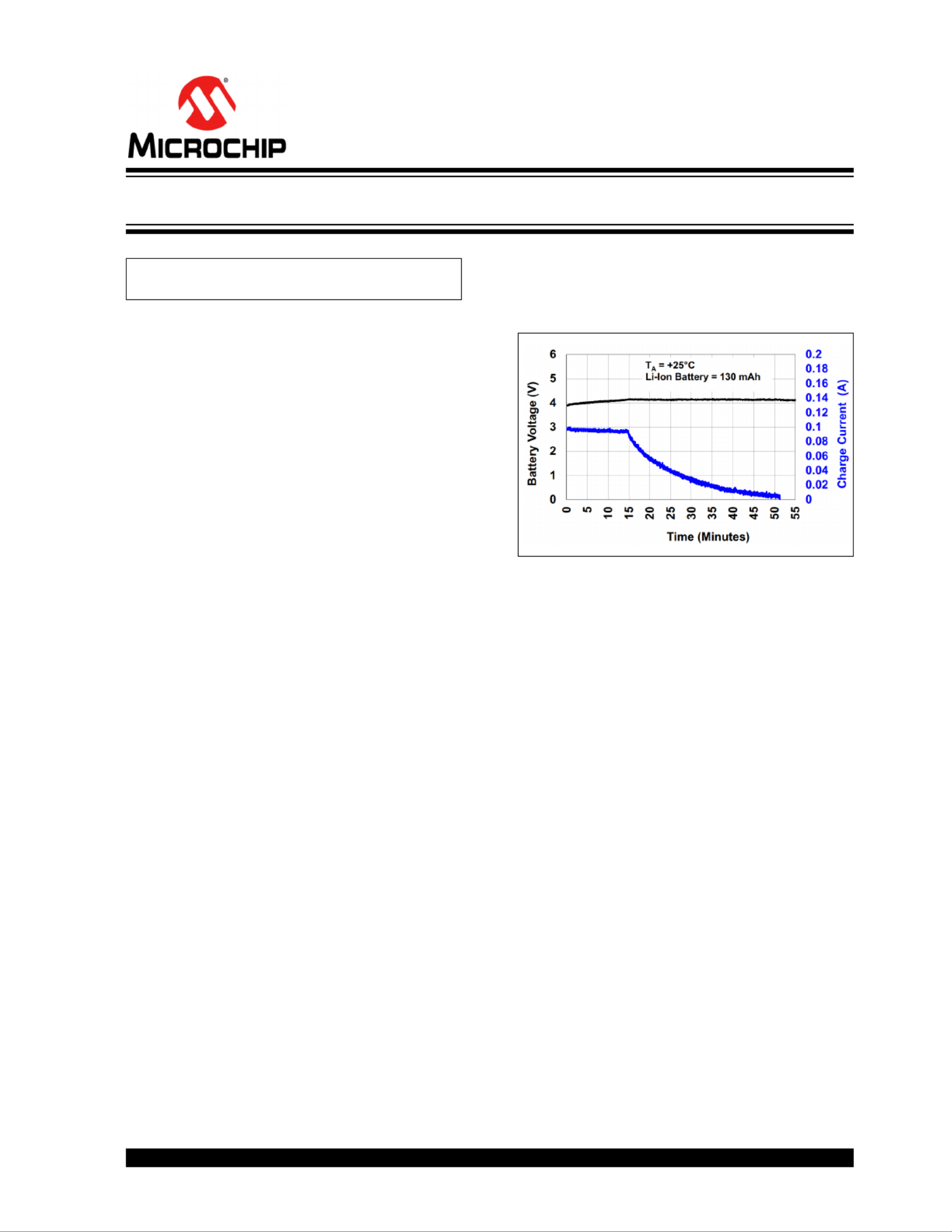
As a general trend, rechargeable batteries are often
used due to their cost effectiveness over their useful life
span. A typical charging profile for Li-Ion batteries is
depicted in Figure 1.
FIGURE 1:Typical Charging Profile
(Li-Ion Battery).
DESIGN CONSIDERATIONS
Input Voltage Range
MCP73830 is a dedicated single cell charger for Li-Ion/
Li-Polymer batteries with a 6V maximum input voltage
range. In order to extend this range up to 30V, the
MCP16311/2 synchronous Buck converter was
connected in series with the battery charger. Figure 2
reveals the block diagram, which also includes the
external compensation block; the proposed application
circuit is detailed in Figure 3.
Charge Qualification for MCP73830
When power is applied, the input supply must rise
150 mV above the battery voltage, before the
MCP73830 device becomes operational. The
automatic power-down circuit sets the device in
Shutdown mode if the input supply falls within +50mV
of the battery voltage; the automatic circuit is always
active. Whenever the input supply is within +50 mV of
the voltage at the VBATpin, the MCP73830 is set into
Shutdown mode. For a charge cycle to begin, the
automatic power-down exit conditions must be met
(VDD ≥3.6V and VDD ≥VBAT + 150 mV) and the
charge enable input signal level must be above the
input high threshold. In addition to this, the battery
voltage should be less than 96.5% of V
REG. VREGis
factory set to a typical value of 4.2V.
Author:Andreea Macalau
Microchip Technology Inc.
MCP16311/2 and MCP73830 Single-Cell Battery Charger
Specyfikacje produktu
| Marka: | Microchip |
| Kategoria: | Niesklasyfikowane |
| Model: | MCP73830 |
Potrzebujesz pomocy?
Jeśli potrzebujesz pomocy z Microchip MCP73830, zadaj pytanie poniżej, a inni użytkownicy Ci odpowiedzą
Instrukcje Niesklasyfikowane Microchip

15 Stycznia 2025
15 Stycznia 2025
15 Stycznia 2025
15 Stycznia 2025
15 Stycznia 2025
15 Stycznia 2025
15 Stycznia 2025
15 Stycznia 2025
15 Stycznia 2025
15 Stycznia 2025
Instrukcje Niesklasyfikowane
Najnowsze instrukcje dla Niesklasyfikowane
29 Stycznia 2025
29 Stycznia 2025
29 Stycznia 2025
29 Stycznia 2025
29 Stycznia 2025
29 Stycznia 2025
29 Stycznia 2025
29 Stycznia 2025
29 Stycznia 2025
29 Stycznia 2025