Instrukcja obsługi RTS OKI
Przeczytaj poniżej 📖 instrukcję obsługi w języku polskim dla RTS OKI (2 stron) w kategorii nieskategoryzowany. Ta instrukcja była pomocna dla 48 osób i została oceniona przez 9 użytkowników na średnio 4.3 gwiazdek
Strona 1/2
Quick Start Guide
OKI - OMNEO Keypanel Interface KP 12 CLD
Included:
•OMNEOKeypanelModule
•RearPanel,KP12CLD,Expansion
•2-Screw,4-40x.25LG.
•3-Screw,PH,4-40x3/16LG.
•SafetyInstructionsST-CO
•OKIQuickStartGuide
•OKIDocumentationResourceDisk
Requirements:
Youmusthavethefollowing:
•PhillipsScrewdriver
•HexNutDriver
Firmware Requirements
•KP12CLDversion1.30
IMPORTANTThekeypanelrmwaremustbeupdatedbefore
youinstalltheOKImoduleintothekeypanel.
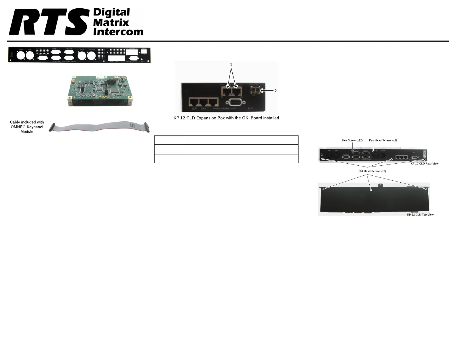
Reference View - OKI KP 12 CLD
Description
1.J1&J2RJ-45Connectors(2)
2.J3LCFiberConnector(Optional)
OKI Installation – KP 12 CLD
Toinstall the OKI board set for the KP 12 CLD,dothe
following:
NOTE:Becauseallthechangesaremadetothe
expansionbox,removetheexpansionboxfrom
theKP12CLDunit.
1.PowerofftheKP12CLDunit.
2.Removetheexpansion boxfromtheKP12CLD
unit.
NOTE:Steps3and4areonlynecessaryifanRCoption
isinstalled.
3.Usingahexnutdriver,removethe12 hex screws
fromtheKP12CLDexpansionbox.
4.Usingthesamescrewdriver,removetheeight (8)
pan head screwsfromtheKP12CLDexpansion
box.
5.UsingaPhillipsscrewdriver,removethesix (6) at
head screwsfrom KP12CLDexpansionbox.
F01U280811Rev0101/2013
Specyfikacje produktu
| Marka: | RTS |
| Kategoria: | nieskategoryzowany |
| Model: | OKI |
Potrzebujesz pomocy?
Jeśli potrzebujesz pomocy z RTS OKI, zadaj pytanie poniżej, a inni użytkownicy Ci odpowiedzą
Instrukcje nieskategoryzowany RTS

14 Września 2024
14 Września 2024
Instrukcje nieskategoryzowany
Najnowsze instrukcje dla nieskategoryzowany
28 Października 2024
28 Października 2024
27 Października 2024
27 Października 2024
27 Października 2024
27 Października 2024
27 Października 2024
27 Października 2024
27 Października 2024
27 Października 2024