Instrukcja obsługi Atdec SD-AT-DK-BK
Atdec Niesklasyfikowane SD-AT-DK-BK
Przeczytaj poniżej 📖 instrukcję obsługi w języku polskim dla Atdec SD-AT-DK-BK (4 stron) w kategorii Niesklasyfikowane. Ta instrukcja była pomocna dla 16 osób i została oceniona przez 6 użytkowników na średnio 4.2 gwiazdek
Strona 1/4
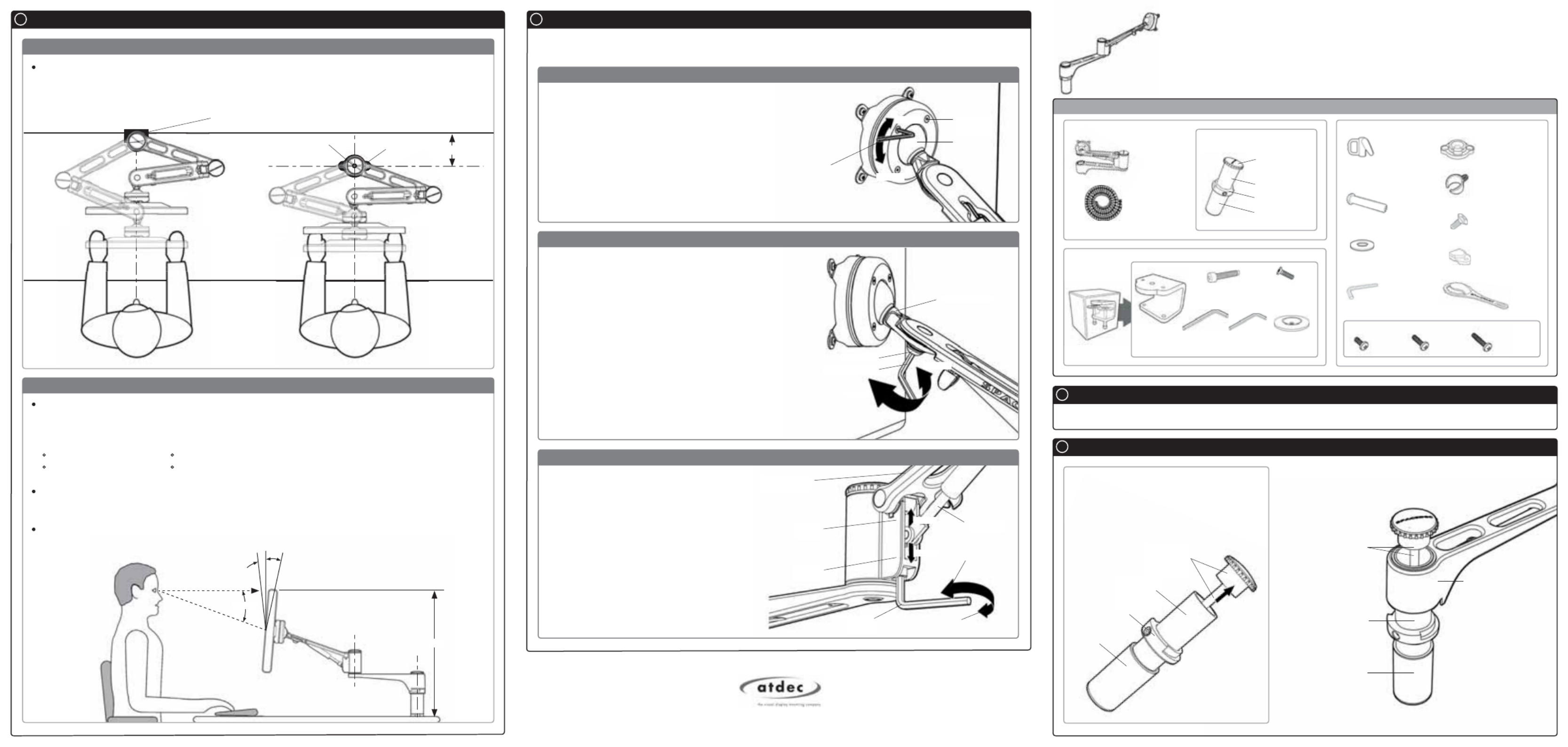
Component Checklist
Installation Instructions
SPACEDEC ACROBAT
SD-AT-DK | ARTICULATED ARM
Single Arm
Articulated Arm
Assembly (x1)
Base Casting (x1)
Cable Wrap
Applicator (x1)
Top Cap Tool (x1)
2.5mm Allen
Key (x1)
16mm Cable
Wrap (x1)
M10 Interscrew (x1)
Cable Clip (x3)
M6x12mm
Countersunk
Screw (x2)
Extension
Clip (x4)
Desk Clamp Box
Desk Clamp
Bracket (x1)
M8 Desk Clamp
Screw (x2)
Pressure
Plate (x2)
Component Checklist
A
Check you have received all parts against the Component Checklist above.
Bits Box
5mm Allen
Key (x1)
Assembling the Arm
B
Adjusting the Display
H
As LCD Manufacturers are constantly releasing new monitor models, Atdec does not accept responsibility if the mounting hole pattern does not comply with the
international VESA standards. Due to continuing product development, the manufacturer reserves the right to alter specifications without notice.
Published: 02.05.12
Installation Complete
14 Gauge Self
Tapping Screw (x2)
B.1. Disassemble the Tube Assembly
In order to attach the Articulated Arm to the
tube assembly you will need to remove the
Top Cap and Threaded Rod as shown:
B.2. Assemble the Articulated Arm
Assemble the Articulated Arm as shown:
Top Cap and
Threaded Rod
Arm Assembly
Internal Tube Post
Spacer
Tube
Top Cap and
Threaded Rod
Internal
Tube Post
Spacer
Tube
Collar
Mounting Fasteners
M4x10mm
Screw (x4)
M4x12mm
Screw (x4)
M4x16mm
Screw (x4)
Tube Assembly (x1)
Threaded Rod
and Top Cap (x1)
Collar
Inner Tube Post
Spacer Tube
Washer (x1)
H.1. Adjusting the Ball Joint Resistance
The Acrobat Articulated Arm comes factory set to support 6kg displays. Adjust the arm to suit the weight of your
display as shown in the following steps:
Depending on the weight of the monitor, it may
be necessary to make adjustments to the Ball Joint
Mechanism. If the monitor doesn’t hold its position or
is too resistant, adjust the four tension screws located
around the Ball Joint (see diagram on the right) using
the supplied 2.5mm Allen Key.
Check the display, and then adjust again if necessary.
NOTE: Be sure to adjust screws evenly.
Tighten
Loosen
Tension
Screws (x4)
Ball Joint
2.5mm
Allen Key
H.2. Adjusting the Pivot Head Resistance
It is possible to control the amount of resistance in the
Pivot Head to suit your display.
To increase the resistant of the Pivot Head to suit heavier
displays, use the 5mm Allen Key supplied in the Desk
Clamp Box to tighten the interscrew in a clockwise
direction.
To decrease the resistance of the Pivot Head to suit
lighter displays, loosen the interscrew in an
anti-clockwise direction.
NOTE: It is recommended the Pivot Head be left
at the factory setting for best performance.
Pivot Head
Interscrew
5mm Allen Key
Loosen
Tighten
H.3. Adjusting the Articulated Arm/Gas Strut Resistance
3kg
Monitor
9kg
Monitor
Arm
Raise Gas
Strut to suit
lighter display
5mm
Allen key
Gas Strut
Lighter
Heavier
Lower Gas Strut to
suit heavier display
4mm Allen
Key (x1)
Ergonomic Guidelines
G
H.3.1. Depending on the weight of the monitor, it
may be necessary to adjust the arm. This can be
done by using the 5mm Allen Key supplied in the
Desk Clamp Box.
H.3.2. If the arm tends to automatically rise or fall
when the display is attached, it will be necessary
to make small adjustments to the gas strut. (see
diagram on the right)
H.3.3. If the arm tends to rise, the gas strut
position should be raised. If the arm tends to fall,
the gas strut position should be lowered.
Ergonomists recommend that the optimal position of your screen should be slightly below eye level.
When looking at the screen’s centre the user should have a downward visual angle of approximately
10°-20°. As a guide, the height (h) of your display should approximately be as follows:
Tall Male (Max): 560mm (22”) Tall Female (Max): 520mm (201/2”)
Short Male (Min): 368mm (141/2”) Short Female (Min): 356mm (14”)
For visual comfort, a viewing distance (d) between 500mm (19
1/2”) to 750mm (291/2”) is
recommended.
Angular adjustments to reduce reflection on your monitor should range between 5° forward tilt to 15°
backward tilt.
Desk Clamp
15°
5°
HORIZONTAL SIGHT LINE (d)
CENTRE OF SCREEN
10°-20°
Recommended Viewing Distance / Height
Recommended Mounting Position
50mm (2”)
When mounting the Spacedec Acrobat Articulated Arm, ensure the correct focal distance can be
achieved for ultimate visual comfort (Refer to Recommended Viewing Distance / Height below)
Desk Clamp Bolt Through
(h)
15mm Hole (9/16 ”) Base Casting
Specyfikacje produktu
| Marka: | Atdec |
| Kategoria: | Niesklasyfikowane |
| Model: | SD-AT-DK-BK |
Potrzebujesz pomocy?
Jeśli potrzebujesz pomocy z Atdec SD-AT-DK-BK, zadaj pytanie poniżej, a inni użytkownicy Ci odpowiedzą
Instrukcje Niesklasyfikowane Atdec

28 Grudnia 2024
7 Grudnia 2024
7 Grudnia 2024
7 Grudnia 2024
3 Października 2024
23 Września 2024
23 Września 2024
22 Września 2024
22 Września 2024
22 Września 2024
Instrukcje Niesklasyfikowane
Najnowsze instrukcje dla Niesklasyfikowane
29 Stycznia 2025
29 Stycznia 2025
29 Stycznia 2025
29 Stycznia 2025
29 Stycznia 2025
29 Stycznia 2025
29 Stycznia 2025
29 Stycznia 2025
29 Stycznia 2025
29 Stycznia 2025