Instrukcja obsługi Dual 1264
Dual Niesklasyfikowane 1264
Przeczytaj poniżej 📖 instrukcję obsługi w języku polskim dla Dual 1264 (12 stron) w kategorii Niesklasyfikowane. Ta instrukcja była pomocna dla 16 osób i została oceniona przez 8 użytkowników na średnio 4.0 gwiazdek
Strona 1/12
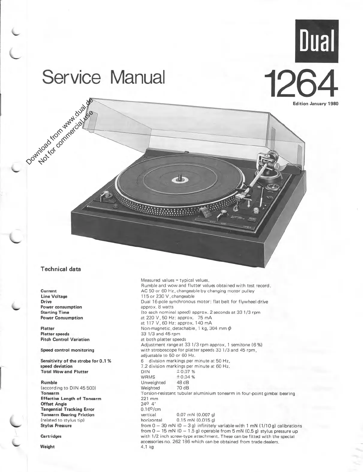
Service
Manual
Technical
data
Current
Line
Voltage
Drive
Power
consumption
Starting
Time
Power
Consumption
Platter
Platter
speeds
Pitch
Control
Variation
Speed
control
monitoring
Sensitivity
of
the
strobe
for
0.1
%
speed
deviation
Total
Wow
and
Flutter
Rumble
(according
to
DIN
45
500)
Tonearm
Effective
Length
of
Tonearm
Offset
Angle
Tangential
Tracking
Error
Tonearm
Bearing
Friction
(related
to
stylus
tip)
Stylus
Pressure
Cartridges
Weight
Dual
1264
Edition
January
1980
Measured
values
=
typical
values.
Rumble
and
vvow
and
flutter
values
obtained
with
test
record.
AC
50
or
60
Hz,
changeable
by
changing
motor
pul
ley
115
or
230
V,
changeable
Dual
16
-pole
synchronous
motor:
flat
belt
for
flywheel
drive
approx.
8
watts
(to
each
nominal
speed)
approx.
2
seconds
at
33
1/3
rpm
at
220
V,50
Hz: approx.
75
mA
at
117
V,60
Hz: approx.
140
mA
Non-magnetic,
detachable,
1
kg,
304
mm
q5
33
1/3
and
45
rpm
at
both
platter
speeds
Adjustment
range
at
33
1/3
rpm
approx.
1
semitone
(6
%)
with
stroboscope
for
platter
speeds
33
1/3
and
45
rpm,
adjustable
to
50
or
60
Hz.
6
division
markings
per
minute
at
50
Hz,
7.2
division
markings
per
minute
at
60
Hz.
DIN
±
0.07
%
WRMS
±
0.04
%
Unweighted
48
dB
Weighted
70
dB
Torsion-resistant
tubular
aluminium
tonearm
in
four-point
gimbal
bearing
221
mm
24
0
4'
0.16
0
/cm
vertical
0.07
mN
(0.007
g)
horizontal
0.15
mN
(0.015
g)
from
0
—
30
mN
(0
—
3
g)
infinitely
variable
with
1
mN
(1/10
g)
calibrations
from
0
—
15
mN
(0
—
1.5
g)
operable
from
5
mN
(0.5
g)
stylus
pressure
up
with
1/2
inch
screw-type
attachment.
These
can
be
fitted
with
the
special
accessories
no.
262
186
which
can
be
obtained
from
trade
dealers.
4.1
kg
Download from www.dual.de
Not for commercial use
Specyfikacje produktu
| Marka: | Dual |
| Kategoria: | Niesklasyfikowane |
| Model: | 1264 |
Potrzebujesz pomocy?
Jeśli potrzebujesz pomocy z Dual 1264, zadaj pytanie poniżej, a inni użytkownicy Ci odpowiedzą
Instrukcje Niesklasyfikowane Dual

3 Stycznia 2025
3 Stycznia 2025
3 Stycznia 2025
3 Stycznia 2025
3 Stycznia 2025
3 Stycznia 2025
2 Stycznia 2025
3 Października 2024
3 Października 2024
3 Października 2024
Instrukcje Niesklasyfikowane
Najnowsze instrukcje dla Niesklasyfikowane
29 Stycznia 2025
29 Stycznia 2025
29 Stycznia 2025
29 Stycznia 2025
29 Stycznia 2025
29 Stycznia 2025
29 Stycznia 2025
29 Stycznia 2025
29 Stycznia 2025
29 Stycznia 2025