Instrukcja obsługi Dual C 806
Dual Niesklasyfikowane C 806
Przeczytaj poniżej 📖 instrukcję obsługi w języku polskim dla Dual C 806 (14 stron) w kategorii Niesklasyfikowane. Ta instrukcja była pomocna dla 32 osób i została oceniona przez 3 użytkowników na średnio 4.3 gwiazdek
Strona 1/14
C=3
=Ih
Dual
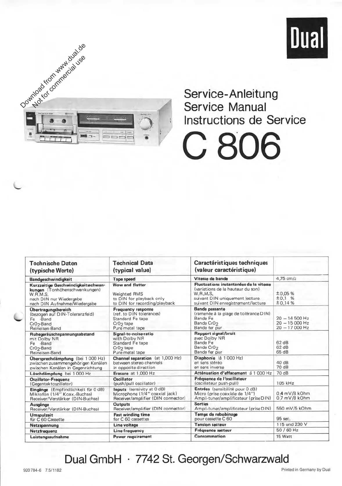
Service
-Anleitung
Service
Manual
Instructions
de
Service
806
Technische
Daten
(typische
Werte)
Technical
Data
(typical
value)
Caractdristiques
techniques
(valeur
caractöristique)
Bandgeschwindigkeit
Tape
speed
Vitesse
de
bande
4,75
cm/3
Kurzzeitige
Geschwindigkeitsschwan-
kungen
(Tonhöhenschwankungen)
W.R.M.S.
nach
DIN
nur
Wiedergabe
nach
DIN
Aufnahme/Wiedergabe
Wow
and
flutter
Weighted
RMS
to
DIN
for
playback
only
to
DIN
für
recording/playback
Fluctuations
instantandes
de
la
vitesse
(variations
de
la
hauteur
du
son)
W.R.M.S.
suivant
DIN
uniquement
lecture
suivant
DIN
enregistrement/lecture
±
0,05
%
±0,1
%
±
0,14
%
Übertragungsbereich
(bezogen
auf
DIN
-Toleranzfeld)
Fe
-Band
Cr02-Band
Reineisen-Band
Frequency
response
(ref.
to
DIN
tolerances)
Standard
Fe
tape
Cr02
tape
Pure
metal
tape
Bande
passante
(ramenäe
ä
la
plage
de
tolärance
DIN)
Bande
Fe
Bande
Cr02
Bande
fer
pur
20
—
14
500
Hz
20
—
15
000
Hz
20
—
17
000
Hz
Ruhegeräuschspannungsabstand
mit
Dolby
NR
Fe
-Band
Cr02-Band
Reineisen-Band
Signal-to-noise-ratio
with
Dolby
NR
Standard
Fe
tape
Cr02
tape
Pure
metal
tape
Rapport
signal/bruit
avec
Dolby
NR
Bande
Fe
Bande
Cr02
Bande
fer
pur
62
dB
62
dB
65
dB
Übersprechdämpfung
(bei
1
000
Hz)
zwischen
zusammengehörigen
Kanälen
zwischen
Kanälen
in
Gegenrichtung
Channel
separation
(at
1,000
Hz)
between
stereo
channels
in
opposite
direction
Diaphonie
lä
1
000
Hz)
en
sens
stäräo
en
sens
inverse
40
dB
70
dB
Löschdämpfung
bei
1
000
Hz
Erasure
at
1,000
Hz
Atenuation
d'effacement
ä
1
000
Hz
70
dB
Oszillator-Frequenz
(Gegentaktoszillator)
Oscillator
(push/pull
oscillator)
Frdquence
de
l'oscillateur
(oscillateur
push
-pull)
105
kHz
Eingänge
(Empfindlichkeit
für
0
dB)
Mikrofon
(1/4"
Koax.-Buchse)
Receiver/Verstärker
(DIN-Buchse)
Inputs
(sensivity
at
0
dB)
Microphone
(1/4"
coaxial
jack)
Receiver/amplifier
(DIN
connector)
Enteees
(sensibilitä
pour
0
dB)
Micro
(prise
coaxiale
de
1/4")
Ampli-tuner/amplificateur
(priseD
IN)
0,4
mV/8
kOhm
0,7
mV/8
kOhm
Ausgänge
Receiver/Verstärker
(DIN-Buchse)
Outputs
Receiver/amplifier
(DIN
connector)
Sorties
Ampli-tuner/amplificateur
(priseD
IN)
550
mV/5
kOhm
Umspulzeit
für
C
60
Cassette
Fast
winding
time
für
C
60
cassettes
Temps
de
rebobinage
pour
cassette
C
60
95
sec.
Netzspannung
Line
voltage
Tension
secteur
115
und
230
V
Netzfrequenz
Line
f
requency
Frdquence
secteur
50
/
60
Hz
Leistungsaufnahme
Power
requirement
Consommation
15
Watt
920784-6
7.5/1182
Dual
GmbH
•
7742
St.
Georgen/Schwarzwald
Printed
in
Germany
by
Dual
Download from www.dual.de
Not for commercial use
Specyfikacje produktu
| Marka: | Dual |
| Kategoria: | Niesklasyfikowane |
| Model: | C 806 |
Potrzebujesz pomocy?
Jeśli potrzebujesz pomocy z Dual C 806, zadaj pytanie poniżej, a inni użytkownicy Ci odpowiedzą
Instrukcje Niesklasyfikowane Dual

3 Stycznia 2025
3 Stycznia 2025
3 Stycznia 2025
3 Stycznia 2025
3 Stycznia 2025
3 Stycznia 2025
2 Stycznia 2025
3 Października 2024
3 Października 2024
3 Października 2024
Instrukcje Niesklasyfikowane
Najnowsze instrukcje dla Niesklasyfikowane
29 Stycznia 2025
29 Stycznia 2025
29 Stycznia 2025
29 Stycznia 2025
29 Stycznia 2025
29 Stycznia 2025
29 Stycznia 2025
29 Stycznia 2025
29 Stycznia 2025
29 Stycznia 2025