Instrukcja obsługi Dual CST 3510
Dual Niesklasyfikowane CST 3510
Przeczytaj poniżej 📖 instrukcję obsługi w języku polskim dla Dual CST 3510 (6 stron) w kategorii Niesklasyfikowane. Ta instrukcja była pomocna dla 23 osób i została oceniona przez 9 użytkowników na średnio 4.7 gwiazdek
Strona 1/6
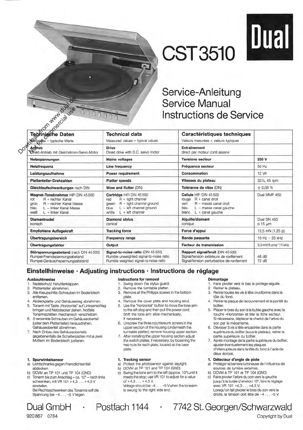
Dual
Service
-Anleitung
Service
Manual
Instructions
de
Service
Technische
Daten
Meßwerte
=
typische
Werte
Technical
data
Measured
values
=
typical
values
Caract6ristiques
techniques
Valeurs
mesuräes
=
valeurs
typiques
Antrieb
Direkt
-Antrieb
mit
Gleichstrom
-Sem
-Motor
Drive
Direkt
drive
with
D.C.
servo
motor
Entrainement
direct
par
moteur
conti
asservi
Netzspannungen
Mains
voltages
Tensions
secteur
230
V
Netzfrequenz
Line
frequency
Frequence
secteur
..
50
Hz
Leistungsaufnahme
Power
requirement
Consommation
12
VA
Plattenteller
-Drehzahlen
Platter
speeds
Vitesses
du
plateau
33
1/2
,
45
rpm
Gleichlaufschwankungen
nach
DIN
Wow
and
flutter
(DIN)
Toterence
de
vites
(DIN)
±
0,06
%
Magnet
-Tonabnehmer
HiFi
DIN
45
500
rot
R
+
rechter
Kanal
grün
R
-
rechter
Kanal
Masse
blau
L
-
linker
Kanal
Masse
weiß
L
+
linker
Kanal
Cartridge
HiFi
DIN
45
500
red
R
+
right
channel
green
R
-
right
channel
ground
blue
L
-
left
channel
ground
white
L
+
left
channel
Cellule
HIFI
DIN
45
500
rouge
R
+
canal
droit
vert
R
-
masse
canal
droit
bleu
L
-
masse
canal
gauche
blanc
L
+
canal
gauche
Dual
MMP
450
Diamantnadel
konisch
Diamond
stylus
conical
Aiguille/diamant
conique
Dual
DN
450
0
15
ihm
Empfohlene
Auflagekraft
Ttacking
force
Force
d'appui
12,5
mN
(1,25
p)
Übertragungsbereich
Frequency
range
Bande
passante
10
Hz
-
25
kHz
Übertragungsfaktor
Output
Facteur
de
transmission
3,5
mV/5
cms
-1
/
1
kHz
Störspannungsabstand
(nach
DIN
45500)
Rumpel-Fremdspannungsabstand
Rumpel-Geräuschspannungsabstand
Signal-to-noise
ratio
(DIN
45500)
Rumble
unweighted
signal-to-noise
ratio
Rumble
weighted
signal-to-noise
ratio
Rapport
signaVbruit
(DIN
45500)
SignaVtension
extärieure
de
ronflement
SignaVtension
perturbatrice
de
ronflement
46
dB
72
dB
Einstellhinweise
•
Adjusting
instructions
•
Instructions
de
röglage
Ausbauhinweise
1.
Nadelschutz
herunterklappen.
2.
Plattenteller
abnehmen.
3.
Alle
Kreuzschlitz
-Schrauben
im
Bodenblech
entfernen.
4.
Abdeckplatte
und
Gehäusesteg
abnehmen.
5.
Tonarm
mit
Taste
„Horizontal"
auf
Unksanschlag
bringen
und
Netzstecker
ziehen.
Notfalls
Tonarmschlitten
mechanisch
verschieben.
6.
3
versenkte
Schrauben
im
Gehäuseoberteil
(unter
dem
Plattenteller)
herausdrehen,
Gehäuseoberteil
abnehmen.
7.
Nach
Einbau
des
Gehäuseoberteils
gegebenenfalls
die
Schalterplatten
mit
je
zwei
Muttern
im
Bodenblech
justieren.
1.
a)
b)
c)
Spunvinkelsensor
Lichtschranke
gegen
Fremdlichteinfall
abdecken.
DCVM
an
TP
101
und
TP
104
(GND)
Tonarm
bis
zum
Anschlag
-
ca.
10°-
nach
links
schwenken,
mit
VR
101
+4,3.
. .
+
4,5
V
einstellen.
Bei
Rechtsschwenken
des
Tonarms
soll
die
Spannung
bei
-4.
. .
-5
V
liegen.
Instructions
for
removal
1.
Swing
down
the
stylus
guard.
2.
Remove
the
tumtable
platter.
3.
Remove
all
the
Philipps
screws
in
the
bottom
plate.
4.
Remove
the
cover
plate
and
housing
strut.
5.
Use
the
"horizontal"
button
to
move
the
tone
arm
to
the
left
stop
and
then
pull
the
power
cord.
Shift
the
tone
arm
slide
mechanically,
if
necessary.
6.
Unscrew
the
three
countersunk
screws
in
the
upper
section
of
the
housing
(undemeath
the
tumtable
platter);
remove
housing
upper
section.
7.
After
Installing
the
upper
housing
section
adjust
the
svech
plates,
if
necessary,
by
loosening
the
two
nuts
for
each
plate,
located
at
the
base
plate.
1.
Trecking
sensor
a)
Protect
the
photosensor
against
daylight.
b)
DCVM
at
TP
101
and
TP
104
(GND)
c)
Swing
the
tone
arm
to
the
left
(approx.
10°)
until
it
meets
the
stop;
use
VR
101
to
adjust
for
a
value
of
+
4.3
.
. .
+
4.5
V.
Voltage
should
be
-4.
.
.
-5
Vwhen
the
tonearm
is
swung
to
the
right
side
end.
Demontage
1.
Faire
pivoter
vers
le
bas
le
protäge-aiguille.
2.
Retirer
le
plateau.
3.
Retirer
toutes
les
vis
ä
töte
cruciforme
dans
la
töle
du
fond.
4.
Retirer
la
plaque
de
recouvrement
et
le
pontöt
du
boitier.
5.
Placer
le
bras
du
son
ä
la
butäe
gauche
avec
la
touche
«Horizontal»
et
tirer
la
frohe
secteur.
Si
näcessaire,
deleoer
le
chariot
de
l'arbre
du
son
par
le
mäcanisme.
6.
Dävisser
3
vis
ä
töte
encasträe
dans
la
partie
supärieure
du
boitier
(sous
le
plateau),
retirer
la
partie
supörieure
du
boitier.
7.
Apräs
montage
de
la
partie
supärieure
du
boitier,
ajuster
äventuellement
les
plaques
d'interrupteurs
dans
la
töle
du
fond
ä
l'aide
de
deux
krous.
1.
Detecteur
d'angle
de
piste
a)
Protäger
la
barriere
lumineuse
de
l'
influence
de
sources
de
lumiäre
externes.
b)
DCVM
ä
TP
101
et
TP
104
(GND)
c)
Faire
pivoter
l'arbre
du
son
vers
la
gauche
jusqu'ä
la
butäe
d'environ
10°,
faire
le
räglage
avec
VR
101
+4,3.
..
+4,5V.
Lorsqu'on
fait
pivoter
le
bras
du
son
vers
la
droite,
la
tension
doit
ötre
de
-4.
. .
-5V.
Dual
GmbH
•
Postfach
1144
920
867
0784
7742
St.
Georgen/Schwarzwald
Copyright
by
Dual
Download from www.dual.de
Not for commercial use
Specyfikacje produktu
| Marka: | Dual |
| Kategoria: | Niesklasyfikowane |
| Model: | CST 3510 |
Potrzebujesz pomocy?
Jeśli potrzebujesz pomocy z Dual CST 3510, zadaj pytanie poniżej, a inni użytkownicy Ci odpowiedzą
Instrukcje Niesklasyfikowane Dual

3 Stycznia 2025
3 Stycznia 2025
3 Stycznia 2025
3 Stycznia 2025
3 Stycznia 2025
3 Stycznia 2025
2 Stycznia 2025
3 Października 2024
3 Października 2024
3 Października 2024
Instrukcje Niesklasyfikowane
Najnowsze instrukcje dla Niesklasyfikowane
29 Stycznia 2025
29 Stycznia 2025
29 Stycznia 2025
29 Stycznia 2025
29 Stycznia 2025
29 Stycznia 2025
29 Stycznia 2025
29 Stycznia 2025
29 Stycznia 2025
29 Stycznia 2025