Instrukcja obsługi Duronic TM51
Przeczytaj poniżej 📖 instrukcję obsługi w języku polskim dla Duronic TM51 (4 stron) w kategorii Kable do komputerów PC i urządzeń peryferyjnych. Ta instrukcja była pomocna dla 30 osób i została oceniona przez 2 użytkowników na średnio 4.1 gwiazdek
Strona 1/4
07
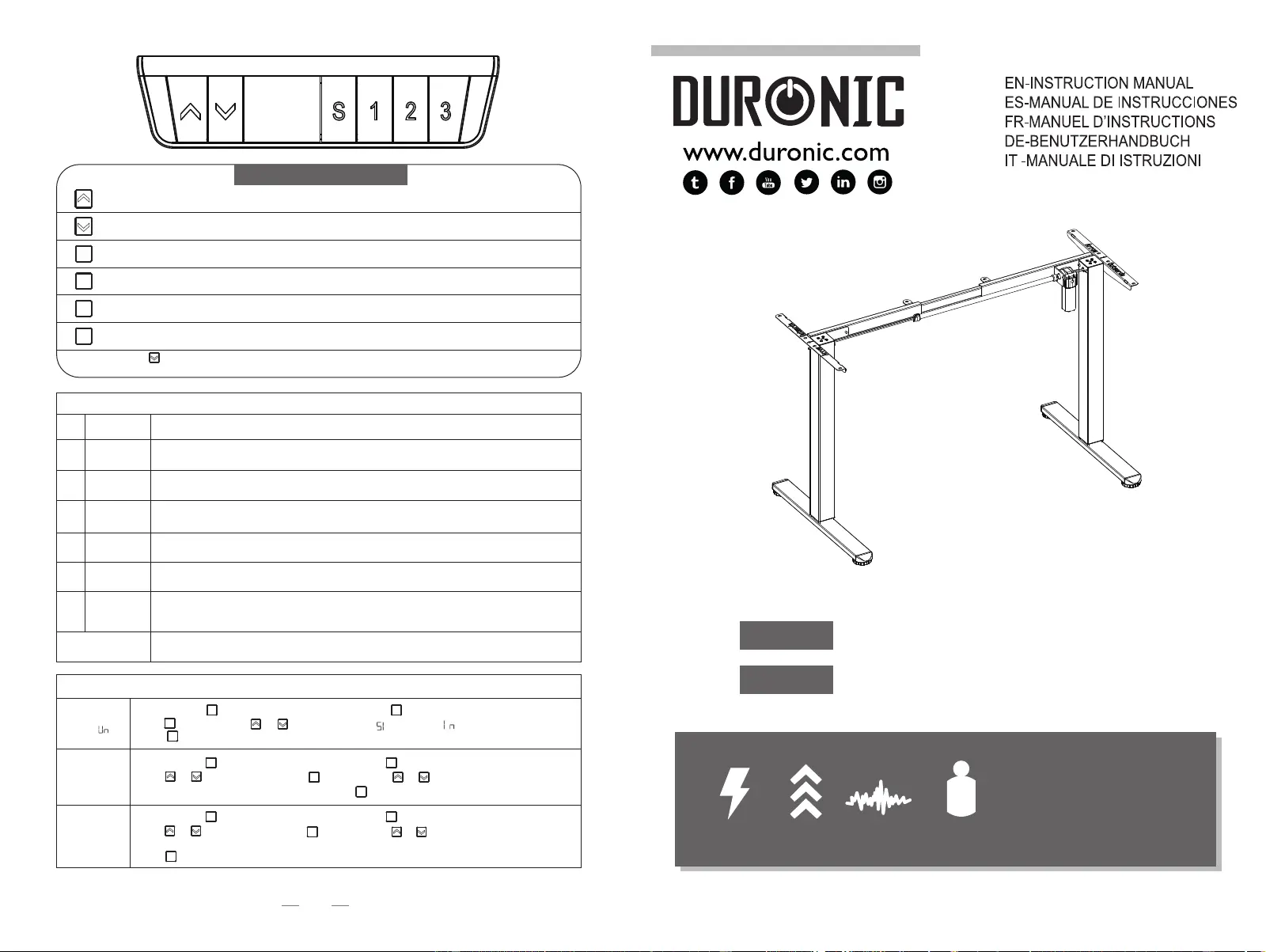
CAUTION: DO NOT EXCEED
MAXIMUM LISTED WEIGHT
CAPACITY.SERIOUS INJURY
OR PROPERTY DAMAGE MAY
OCCUR!
Power Input
100V-240V
Speed
20 mm/s
Load Capability
154 lbs / 70 kg
Motion Noise
<55dB
RATED
Adjust the desk upwards
Adjust the desk downwards
Height Preset 1
Height Preset 2
Height Preset 3
Press for 5 seconds, the display will show 'RES' keep pressing the key until the legs move down to
the lowest position.
To set Height Preset, press the S button until the LED Display flashes then press Preset 1, 2, 3 to
program preset.
S
1
3
2
Reset
Protection mode (auto lock screen mode)
Control Panel Keys
Over-heating
Hot
E10
E20
E02
E32
E31
E60
protection
Detection
alarm
Overload
protection
Rebound
protection
Overvoltage
alarm
Undervoltage
alarm
Step out
alarm
Breaking
protection
Alarms when continuously in motion for 2 minutes.
Power back on and wait for at least 18 minutes before adjusting height again.
Alarms when motor sensor cannot be detected.
Turn off power, check the connection of motor and control box, and then power back on.
If alarm sounds when the desk is moving up, remove loads off the desk and try again.
Alarms when vibrated, collided or inclined during height adjustment. Check if there is anything
in the way of desk motion. Then proceed to the reset the motor.
If it alarms when desk is moving down, turn off the power, remove loads off the desk and re-try.
It alarms when voltage is higher than anticipated value. Turn the power off, check the connection
between power and control box. If no problem, power it back on.
It alarms when voltage is lower than required value. Turn the power off, check the connection
between power and control box. If no problem, power it back on.
It alarms when height difference between left leg and right leg exceeds the set value.
Power off first. Check whether the left leg and the right leg are in the same height. If not, re-do
Installation Step 3 to make them same height. Power it back on.
It stops and enters protection state when motor cables or manual control cables are removed
or disconnected accidentally; goes back to normal after it’s reconnected and alarm is cleared.
Engineering Mode
ChangeDisplayed
Unit()
Change
Brightness(br)
CollisionForce
Detection(CF)
Long press the button, “S--”shows and flashes. Press again and the displayshows “Un”.
shows “Un”.
“OFF”, Low (L), Normal (n) or Heavy (H) collision force detection.
SS
Press to save your choice.
S
Low (L), Normal (n) or High (H) brightness.
Press to save your choice.
S
Long press the button, “S--”shows and flashes. Press again and the display
SS
shows “Un”. Long press the button, “S--”shows and flashes. Press again and the display
SS
Press to save your choice.
S
Press or to switch to
“CF”. Press to select. Press or to switch between
S
Press or to switch to
“br”. Press to select. Press or to switch between
S
Press to select. Press
or to switch between“ ”(metric) or “ ” (imperial).
S
●
Length Adjustment Range: 95-135cm
●Height Adjustment Range: 72-118cm
●
3-Level Height Memory Function
TM51 BK
TM51 WE
Specyfikacje produktu
| Marka: | Duronic |
| Kategoria: | Kable do komputerów PC i urządzeń peryferyjnych |
| Model: | TM51 |
Potrzebujesz pomocy?
Jeśli potrzebujesz pomocy z Duronic TM51, zadaj pytanie poniżej, a inni użytkownicy Ci odpowiedzą
Instrukcje Kable do komputerów PC i urządzeń peryferyjnych Duronic

28 Września 2024
28 Września 2024
28 Września 2024
28 Września 2024
28 Września 2024
28 Września 2024
28 Września 2024
28 Września 2024
28 Września 2024
28 Września 2024
Instrukcje Kable do komputerów PC i urządzeń peryferyjnych
Najnowsze instrukcje dla Kable do komputerów PC i urządzeń peryferyjnych
29 Stycznia 2025
12 Stycznia 2025
10 Stycznia 2025
4 Stycznia 2025
2 Stycznia 2025
2 Stycznia 2025
2 Stycznia 2025
2 Stycznia 2025
1 Stycznia 2025
30 Grudnia 2025