Instrukcja obsługi Fibaro Roller Shutter FGRM-222
Fibaro Niesklasyfikowane Roller Shutter FGRM-222
Przeczytaj poniżej 📖 instrukcję obsługi w języku polskim dla Fibaro Roller Shutter FGRM-222 (2 stron) w kategorii Niesklasyfikowane. Ta instrukcja była pomocna dla 23 osób i została oceniona przez 4 użytkowników na średnio 4.6 gwiazdek
Strona 1/2
ENG
Fibaro Roller Shutter is a universal, Z-Wave compatible, electric
motor controller. The device allows for controlling motors of roller
blinds, awnings, venetian blinds, gates and others, which are single
phase AC powered. Fibaro Roller Shutter allows for precise
positioning of a roller blind or venetian blind lamellas. Precise
positioning is available for the motors equipped with mechanic and
electronic end switches.
The module may be controlled wirelessly, through the Z-Wave
network main controller, or through the switch keys connected to it.
It’s also possible to combine few devices into groups of devices,
which then can be controlled simultaneously. In addition, Fibaro
Roller Shutter is equipped with Power Metering.
SPECIFICATIONS
Power Supply
Supplied motor type
Supported limit switches type
Power of supplied motor
In accordance
with EU standards
Circuit Temperature limit
Operational Temperature
For installation in boxes
Radio protocol
Radio Frequency
Radio signal power
Range
Dimensions (L x W x H)
Electricity consumption
110 - 230 V ±10% 50/60Hz
Single phase, VAC
Electronic and mechanic
up to 1kW for 230V
up to 500W for 110V
LVD (2006/95/EC)
EMC (2004/10B/EC)
R&TTE(1999/5/EC)
105 °C
0 - 40 °C
Ø ≥ 50mm
Z-Wave
868,4 MHz EU;
908,4 MHz US;
921,4 MHz ANZ;
869,2 MHz RU;
1mW
up to 100m outdoors
up to 30m indoors
(depending on building materials
used)
42 x 37 x 17 mm
< 0,8W
TECHNICAL INFORMATION
• Controlled by Fibaro System devices or any Z-Wave controller
• Microprocessor control
• Executive elements: relays
• The device may be operated by momentary or toggle switches,
and by dedicated roller blind control switches
• Connected motor’s current and historical power consumption
measured
WARNING
Danger of electrocution! Any work on the device
regarding electrical connections may be performed
only after the power supply has been
disconnected.
OPERATING MANUAL
FIBARO ROLLER SHUTTER
FGRM-222-EN-A-v1.00
I. GENERAL INFORMATION ABOUT FIBARO SYSTEM
Fibaro is a wireless system, based on Z-Wave technology. Fibaro
provides many advantages when compared to similar systems. In
general, radio systems create a direct connection between the
receiver and transmitter. However, a radio signal is weakened by
various obstacles located in its path (apartment walls, furniture,
etc.) and in extreme cases it fails to transfer required data. The
advantage of Fibaro System is that its devices, apart from being
transmitters and signal receivers, also duplicate signal. When a
direct connection path between the transmitter and the receiver
cannot be established, the connection may be achieved through
other intermediate devices.
Fibaro is a bi-directional wireless system. This means that the
signal is not only sent to the receivers but also the receivers send
the confirmation of its reception. This operation confirms their
status, which checks whether they are active or not. Safety of the
Fibaro System transmission is comparable to the safety of
transmission in data bus wired systems.
Fibaro operates in the free bandwidth for data transmission. The
frequency depends on radio regulations in individual countries.
Each Fibaro network has its own unique network identification
number (home ID), which is why it is possible to co-operate two or
more independent systems in a single building without any
interference.
Although Z-Wave is quite a new technology, it has already become
recognized and officially a binding standard, similarly to Wi-Fi.
Many manufacturers in various industries offer solutions based on
Z-Wave technology, guaranteeing their compatibility. This means
that the system is open and it may be extended in the future. Find
more information at www.fibaro.com.
Fibaro generates a dynamic network structure. After Fibaro System
is switched on, the location of its individual components is
automatically updated in real-time through status confirmation
signals received from devices operating in a "mesh" network.
II. ROLLER SHUTTER INSTALLATION
1. Before installation make sure the voltage supply is
disconnected.
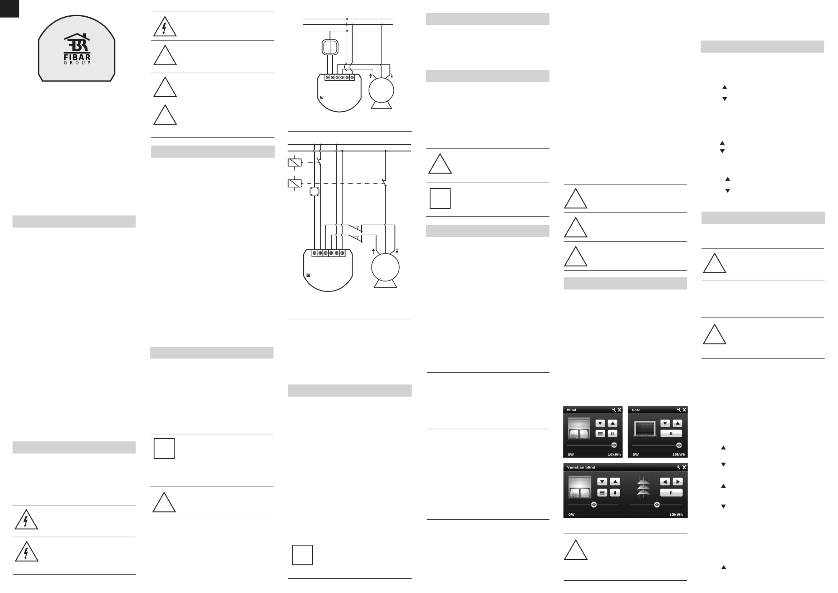
2. Connect the Roller Shutter in accordance with the wiring
diagram presented on Fig. 1 (roller blinds, venetian blinds) or
Fig. 2 (gates).
3. Place the device in a switch box.
4.Arrange the antenna (tips presented below Fig.2)
5. Turn on the power supply keeping the necessary safety
precautions.
6. Include the module into the Z-Wave network, observing pt. III
description.
7. If necessary, calibrate the module, observing pt. VI descripion.
NOTES FOR THE DIAGRAM:
L - terminal for live lead
N - terminal for neutral lead
S1 - terminal for key no. 1 (has the option of entering the device in
learning mode)
S2 - terminal for key No. 2
O1 - output terminal no. 1 for shutter motor
O2 - output terminal no. 2 for shutter motor
B - service button (used to add or remove a device from the
system)
ROLLER BLIND POSITIONING CALIBRATION
TIPS FOR ARRANGING THE ANTENNA
1. Locate the antenna as far from metal elements as possible
(connection wires, bracket rings, etc.) in order to prevent
interferences.
2. Metal surfaces in direct vicinity of the antenna (e.g. metal switch
boxes, door frames) may impair radio signal reception!
3. Do not cut or shorten the antenna. Its length is perfectly
matched to the band in which the system operates.
NOTE
A push button connected to S1 terminal operates
the O1 output, while the push button connected to
S2 terminal operates the O2 output. It’s recommen-
ded to connect an UP button to S1 terminal and a
wire, responsible of up movement, to O1 output
terminal. Respectively, a DOWN button should be
connected to S2 terminal and a wire, responsible
for down movement, to O2 output terminal.
i
WARNING
Fibaro Roller Shutter is dedicated to operate with
AC powered electric motors. Connecting the device
directly to DC powered motors may result in them
being damaged.
Fig. 3 Roller Shutter icons in Home Center interface
WARNING
Danger of electrocution! Even when the device is
turned off, voltage may be present at it’s terminals.
Any work on the device regarding electrical
connections may be performed only after the
power supply has been disconnected.
WARNING
Any maintenance work on controlled devices may
be performed only after the power supply has been
disconnected.
WARNING
It’s not recommended to operate all of the roller
blinds simultaneously. For safety reasons, at least
one roller blind should be controlled independently,
providing safe escape route in case of emergency.
WARNING
Do not connect the device to loads exceeding
recommended value.
Fig. 1 Roller Shutter wiring diagram
III. Z-WAVE NETWORK INCLUSION
Fibaro Roller Shutter may be included into the Z-Wave network via
the B-button or a push button connected to the S1 terminal. In
addition, the module may be included in auto inclusion mode, by
simply connecting the power supply.
Automatic Z-Wave network inclusion:
1) Make sure the power supply is disconnected and a Roller Shutter
is located within a direct Z-Wave network’s main controller
communication range.
2) Set the main controller into the learn mode (see main controllers
operating manual).
3) Connect the power supply to include the Roller Shutter in auto
inclusion mode.
4) Fibaro Roller Shutter will be automatically detected and included
into the Z-Wave network.
To disable the auto inclusion mode, press the B-button briefly, after
connecting the module to the power supply.
Manual Z-Wave network inclusion:
1) Connect the power supply.
2) Set the main controller into the learn mode (see main controllers
operating manual).
3) Triple click the B-button or a push button connected to the S1
terminal.
4) Fibaro Roller Shutter will be detected and included into the
Z-Wave network.
IV. Z-WAVE NETWORK EXCLUSION
Excluding Fibaro Roller Shutter from the Z-Wave network:
1) Make sure the module is connected to the power supply.
2) Set the main controller into the learn mode (see main controllers
operating manual).
3) Triple click the B-button or a push button connected to the S1
terminal.
V. ROLLER SHUTTER RESET
Reset procedure clears the modules’ EPROM memory, including all
information about the Z-Wave network controller, calibration and
power consumption data.
1) Make sure the module is connected to the power supply.
2) Press and hold the B-button for ca. 14 seconds.
3) LED indicator will glow yellow.
4) Release the B-button and press it again, briefly.
5) The Roller Shutter memory is now empty.
6) The module goes into the auto inclusion mode, until any button
is pushed.
NOTE
Memory reset does not remove the module from
the Z-Wave network main controller’s memory.
Prior to memory reset it’s recommended to exclude
the module from the Z-Wave network.
TIP
After memory reset, the Roller Shutter goes into the
auto inclusion mode and waits to be included into
the Z-Wave network. To exit the auto inclusion
mode press the B-button briefly.
i
Fig. 2 Connecting Roller Shutter to GATE motor
VI. POSITIONING CALIBRATION
Calibration is a process during which a Roller Shutter learns the
position of the limit switches and a motor characteristic. Calibration
is mandatory in order for the Roller Shutter to correctly recognize a
roller blind position. The procedure consists of an automatic, full
movement between the limit switches (up, down, and up again).
There are separate procedures of calibrating roller blind and
lamellas (venetian blind) positioning. Each time the calibration
requires the completion of a full cycle (up and down).
There are 5 procedures of calibrating a Fibaro Roller Shutter to
choose from. Each one gives the same results and the user may
choose which one to execute.
A. Calibration through a Fibaro Home Center 2 interface
1) Make sure the module is connected to the power supply,
according to Fig.1
2) Include the module into the Z-Wave network, according to
section
III of instructions.
3) In Home Center 2 interface choose Fibaro Roller Shutter’s
advanced settings.
4) Click CALIBRATE buttin in the devices advanced settings tab.
5) Roller Shutter performs the calibration process, completing full
cycle - up, down and up again.
6) Using an interface test whether the positioning works correctly.
B. Calibration through the Z-Wave network
1) Make sure the module is connected to the power supply,
according to Fig.1
2) Include the module into the Z-Wave network, according to pt.III
instructions.
3) Set the parameter 29 value to 1.
4) Roller Shutter performs the calibration process, completing full
cycle - up, down and up again.
5) The parameter 29 value will be automatically set to 0.
6) Using an interface test whether the positioning works correctly.
C. Calibration through the switch keys
1) Make sure the module is connected to the power supply,
according to Fig.1, and to the switch keys as well (S1 and S2
inputs).
2) Include the module into the Z-Wave network, according to
section
III of instructions.
3) Press and hold the switch key connected to S1 or S2 input
terminal and release it after at least 3 seconds.
4) Press and hold the same switch key again, and release it after 3
seconds.
5) Now press and hold the same button, for 3 seconds, for the 3rd
time.
6)After pressing and releasing the button for the third time,
automatic calibration sequence will start.
7) Roller Shutter performs the calibration process, completing full
cycle - up, down and up again.
D. Calibration through Menu (B-button)
1) Make sure the module is connected to the power supply,
according to Fig.1
2) Include the module into the Z-Wave network, according to
section
III of instructions.
3) Press and hold the B-button for ca. 6 seconds.
4) LED will glow blue.
5) Release the B-button and press it again, briefly.
6)Roller Shutter performs the calibration process, completing full
cycle - up, down and up again.
CALIBRATING LAMELLAS POSITIONING
IN VENETIAN BLINDS
Apart from calibrating the roller blind position, it’s possible to
calibrate the position of venetian blinds lamellas. After correct
calibration, in case of venetian blinds, it’s possible to set the position
between the limit switches, as well as the lamellas angle. By default,
time of full turn of the lamellas is set to 1,5 seconds. If necessary, it
can be modified following below instructions.
1) Make sure the module is connected to the power supply,
according to Fig.1
2) Include the module into the Z-Wave network, according to section
III of instructions.
3) Calibrate the Roller Shutter, according to the instructions
provided in sections VI.A, VI.B, VI.C, VI.D or VI.E.
4) Set the parameter 10 value to 2 or choose in HC2 interface:
Device Type - Venetian Blind
5)Another device icon, responsible for lamellas operation, will show
up in Home Center 2 interface. In case of any other Z-Wave
network controllers managing the lamellas position is achieved
through pressing and holding a switch key (up or down).
6) By default, time of transition between extreme positions is set to
1 500 ms (1,5 seconds).
7) Turn lamellas between extreme positions. If after full cycle a blind
starts moving up or down, then parameter’s 12 value must be
modified, e.g. to 1 000ms (1 second). Correctly configured
lamellas should not force the blind to move up or down.
NOTE
Roller Shutter needs to be calibrated to work with
any given motor.
NOTE
In Venatian Blind mode, lamellas need to be
calibrated to work with any given motor.
VII. OPERATING THROUGH THE Z-WAVE NETWORK
After including into the Z-Wave network, Fibaro Roller Shutter will
be presented in a Home Center 2 interface as a roller blind icon (see
fig. below). After choosing Venetian Blind device type, a second icon
will show up, responsible for managing lamellas position.
User can choose from the following operating modes:
1. Roller Blind Mode, without positioning
2. Roller Blind Mode, with positioning
3. Venetian Blind Mode
4. Gate Mode, without positioning
5. Gate Mode, with positioning
After choosing one of the above operating modes, device will be
represented in Home Center 2 interface by icons shown in Fig.4. In
addition, each operating mode affects certain parameters settings:
1) Roller blind without positioning (parameter 10 set to 0)
2) Roller blind with positioning (parameter 10 set to 1)
3) Venetian blind (parameter 10 set to 2; parameter 13, set to 2)
4) Gate without positioning (parameter 10 set to 3; parameter 12 set
to 0; parameter 17 set to 0)
5) Gate with positioning (parameter 10 set to 4; parameter 12 set to
0; parameter 17 set to 0)
Opening / Closing a blind is acheved through moving a slider or
pushing a button shown in fig. 3.
In Venetian Blind mode, setting lamellas angle is achieved through
moving a slider or pushing a button shown in fig. 3.
VIII. MANUAL OPERATION
Fibaro Roller Shutter allows for connecting push buttons to S1 and
S2 terminals. These may be momentary or toggle switches,
alternatively. Push buttons are responsible for managing the blind’s
movement.
Using momentary switches:
Clickingbutton connected to S1 terminal, initiates up
movement.
Clickingbutton connected to S2 terminal, initiates down
movement.
If the blind is moving, each click, of any button, will stop the
movement. In addition a button click sends a command frame to I-st
association group devices.
In case of venetian blinds, it’s possible to manage the lamellas
angle. Operating Mode - Venetian Blind, or Parameter 10 value set
to 2.
Holding connected to S1 terminal initiates lamellas rotation up.
Holding connected to S2 terminal initiates lamellas rotation
down.
In addition a button hold sends a Fibar Command Class control
frame to II-nd association group devices.
IX. ASSOCIATIONS
Through an association Fibaro Roller Shutter may control another
Z-Wave network device, e.g. another Roller Shutter, Wall Plug,
Dimmer, Relay Switch, RGBW Controller.
NOTE
Association allows for direct communication
between Z-Wave network devices. Main controller
does not take part in such communication.
Fibaro Roller Shutter provides three association groups:
I association group is triggered through a momentary switch click,
or a toggle switch position change.
II association group is triggered through a momentary switch hold
NOTE
II association group is inactive when toggle
switches are used or in Gate Controller mode
(parameter 10). In case of controlling Venetian
Blinds, control commands are sent in Fibar
Command Class standard.
III association group reports the module status. Only one device
may be assigned to this group, main controller by default. It’s not
recommended to modify this group’s settings.
Fibaro Roller Shutter allows for commanding other Roller Shutters,
associated into I or II association group, through clicking or holding
a switch key. For example, this mechanism allows for operating a
Roller Shutter connected to the switch with a button click, and
operating the devices associated in II association group by a button
hold. In addition, when operating Venetian Blinds, it’s possible to
synchronize many devices.
USING ASSOCIATIONS TO OPERATE ANOTHER
ROLLER SHUTTER OR ANY OTHER Z-WAVE
DEVICE.
I ASSOCIATION GROUP:
Clicking button, connected to S1 terminal will initiate up
movement in associated Roller Shutters, or send Turn On command
frame to the devices associated in I-st association group.
Clicking button, connected to S2 terminal will initiate down
movement in associated Roller Shutters, or send Turn Off command
frame to the devices associated in I-st association group.
II ASSOCIATION GROUP:
Holdingbutton , connected to S1 terminal will move the
connected roller blind up, and after 1 second delay initiate up
movement in associated Roller Shutters, or send Turn On command
frame to the devices associated in II-nd association group.
Holding button, connected to S2 terminal will move the
conected rolled blind down, and after 1 second delay initiate down
movement in associated Roller Shutters, or send Turn Off command
frame to the devices associated in II-nd association group.
NOTE
To abort the calibration process press any key
(connected to S1 or S2) or send a STOP control
frame through the Z-Wave network controller. In
Gate Controller mode the calibration process will
be aborted after disconnecting the S2 terminal.
i
Using toggle switches:
Changing switch key position, connected to S1 terminal,
initiates up movement.
Changing switch keyposition, connected to S2 terminal,
initiates down movement.
Choosing a middle position stops the blind.
!
!
!
!
!
!
!
!
NOTE
Venetian blind lamellas may be only operated by
momentary switches.
!
NOTE
Above operating modes and their default settings
are modified automatically only in Home Center 2
controller. In case of the Z-Wave network
controllers from other manufacturers, these
settings need to be manually adjusted (see section
XV).
!
LNS1 S2
L
N
M
N
O2 O1
safety switch
NC
sensor
NC
Fibaro Roller
Shutter
B
limit
switches
E. Calibration through a Fibar Command Class control frame.
It’s possible to force the calibration process execution through
sending a Fibar Command Class control frame through a Z-Wave
network main controller (see a Fibar Command Class documenta-
tion).
WARNING
It is recomended to monitor regulary operation of
Fibaro Roller shutter in all modes. In case of gate
control mode device, motor limit switches, infrared
barriers and emergency stop should be monitored
and maintained regulary
!
USING ASSOCIATIONS TO OPERATE ROLLER
SHUTTERS CONNECTED TO VENETIAN BLINDS.
Using association mechanism to operating venetian blinds requires
configuring both, I-st and II-nd association groups.
I ASSOCIATION GROUP
Clicking button, connected to S1 terminal will initiate up
movement of the connected venetian blind and other devices
associated in I-st association group.
Fibaro Roller
Shutter
LNS1 S2
L
N
M
N
O2
B
O1
Specyfikacje produktu
| Marka: | Fibaro |
| Kategoria: | Niesklasyfikowane |
| Model: | Roller Shutter FGRM-222 |
Potrzebujesz pomocy?
Jeśli potrzebujesz pomocy z Fibaro Roller Shutter FGRM-222, zadaj pytanie poniżej, a inni użytkownicy Ci odpowiedzą
Instrukcje Niesklasyfikowane Fibaro

30 Grudnia 2025
18 Września 2024
16 Września 2024
15 Września 2024
14 Września 2024
14 Września 2024
13 Września 2024
13 Września 2024
12 Września 2024
11 Września 2024
Instrukcje Niesklasyfikowane
Najnowsze instrukcje dla Niesklasyfikowane
29 Stycznia 2025
29 Stycznia 2025
29 Stycznia 2025
29 Stycznia 2025
29 Stycznia 2025
29 Stycznia 2025
29 Stycznia 2025
29 Stycznia 2025
29 Stycznia 2025
29 Stycznia 2025