Instrukcja obsługi Klein Tools VDV427-110
Klein Tools Niesklasyfikowane VDV427-110
Przeczytaj poniżej 📖 instrukcję obsługi w języku polskim dla Klein Tools VDV427-110 (2 stron) w kategorii Niesklasyfikowane. Ta instrukcja była pomocna dla 30 osób i została oceniona przez 7 użytkowników na średnio 4.0 gwiazdek
Strona 1/2
PLACING BLADE INTO STORAGE COMPARTMENT
1. Hold the Punchdown Tool with the blade storage end facing up (Fig. 3).
2. Insert the blade into the blade storage end (It will extend beyond the tool).
3. Turn the “release blade” dial in a counter-clockwise direction until the blade slides
into place.
4. Release the “release blade” dial; the blade is now secure in the storage compartment.
REMOVING BLADE FROM STORAGE COMPARTMENT
1. Hold the Punchdown Tool with the blade storage end facing down (Fig. 4).
2. Turn the “release blade” dial in a counter-clockwise direction until the blade falls out.
3. Release the “release blade” dial.
ADJUSTING PUNCHDOWN FORCE
Note: Arrow on “Impact” dial aligns with selected force setting.
1. To adjust from LO to HI, rotate dial clockwise (Figure 5).
2. To adjust from HI to LO, rotate the dial counter-clockwise (Figure 6).
Note: See table below for recommended force settings.
Impact (force)
Setting
66 Panel/Block/
Terminal
110 Cross-Connect Panels/
Blocks/Keystones Jacks
Low
24-26 gauge conductorsAll
HI
23 and larger
gauge connectors
DO NOT USE
PUNCHDOWN MULTI-TOOL SPECIAL
INSTRUCTIONS (VDV427-300):
HOOK AND SPUDGER
ACCESS AND STORAGE
To extend hook or spudger from storage nest in side of
punchdown chassis, place finger-nail in notched portion
of the hook or spudger and push away from the tool.
Extend hook or spudger to desired position and
use to manipulate wire and or small components.
To store hook or spudger, gently push the hook
or spudger towards the punchdown chassis until
it is nested in the side of the punchdown chassis.
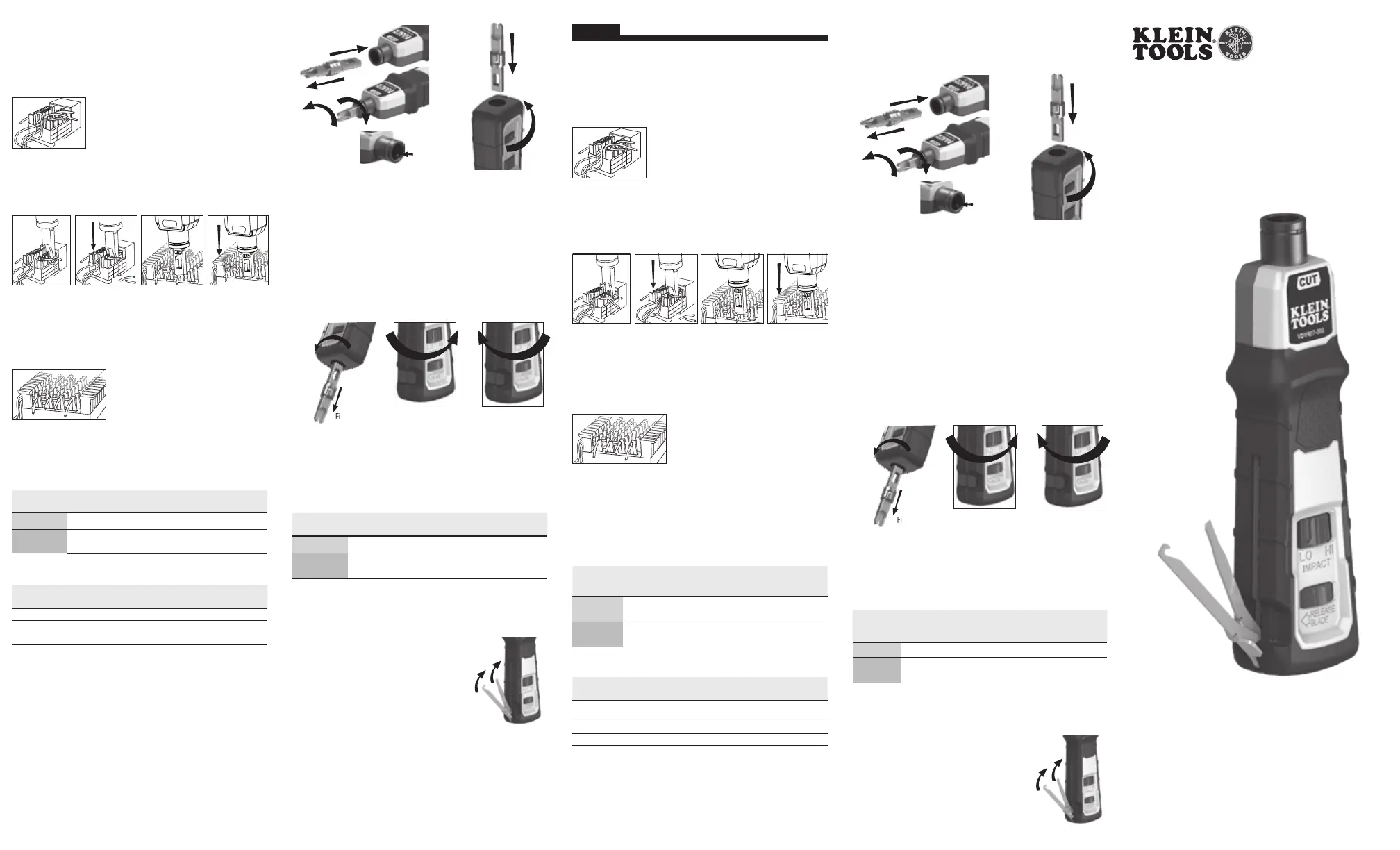
110 TYPE PUNCHDOWN INSTRUCTIONS
1. Insert the 110 terminating blade into the punchdown tool.
2. Choose the correct end of the blade depending on whether or not the wire is to be cut
off. (Figures 10 & 11 show use of the cutting end).
3. Select the proper force setting – LO for all 110 type connections.
4. Lay the wires in the wire slots (see below).
5. Slide the blade into the wire slot and verify the orientation
of the punchdown blade before moving to step 6 (Figure
10). (This is to avoid cutting wire unintentionally during the
punchdown operation; refer to step 2.)
6. Push down on the cushion-grip end of the punchdown
tool with the palm of your hand until it clicks (Figure 11).
7. Slide the blade out of the wire slot and make sure the wire
is properly seated in the bottom of the wire slot between the insulation displacement
connector’s (IDC) blades.
8. Verify that the punchdown tool has seated the wire completely and correctly in the
IDC. Proper use of the punchdown tool should ensure this is done correctly, but it is
always a good idea to verify and test.
66 TYPE PUNCHDOWN INSTRUCTIONS
1. Insert the 66 terminating blade into the punchdown tool.
2. Choose the correct end of the blade depending on whether or not the wire is to be cut
off. (Figures 12 & 13 show use of the cutting end).
3. Select the proper force setting depending on the application. (see table below).
4. Lay the wires in the openings on the post, (see below).
5. Slide the blade over the post and verify orientation of
the punchdown blade before moving to step 6 (Figure
12). (This is to avoid cutting the wire unintentionally
during punchdown operation, refer to step 2.)
6. Push down on the cushion-grip end of the
punchdown tool with the palm of your hand until it
clicks (Figure 13).
7. Slide the blade off of the post and make sure the wire is properly seated at the bottom
of the post between the insulation displacement connector’s (IDC) blades.
8. Verify that the punchdown tool has seated the wire completely and correctly in the IDC.
Proper use of the punchdown tool should ensure this is done correctly, but it is always
a good idea to verify and test.
Impact (force)
Setting
66 Panel/Block/
Terminal
110 Cross-connect Panels
/Blocks/Keystones Jacks
LO
24-26 gauge conductorsAll
HI
23 and larger
gauge connectors
DO NOT USE
Punchdown tools and accessories
Tool / Blade / (Acc.)Blade / Acc.
Cat. No.
Tool with
Blade Cat.No
Impact Punchdown Tool Chassis
N/AVDV427-300
Extended Reach BladeVDV427-110 N/A
DURABLADE
TM
VDV427-104
N/A
INSERTING BLADE
1. Align slot in center of punchdown blade with the pin located on the inside of the
punchdown tool’s barrel and insert blade. (Fig. 1)
2. Rotate blade ¼ turn clockwise (Fig. 2).
Note: When blade is completely seated and locked, the cutting knife (if applicable)
should align with the yellow side of the tool; note “CUT” is imprinted on yellow side
of tool.
REMOVING BLADE
1. Rotate blade 1/4 turn counter-clockwise and pull gently (Fig. 2).
2. Remove blade (Fig. 1).
B
568
B
A
B
A
B
CUT
4
6
8
7
A
CUT
B
568
B
A
4
6
8
7
B
A
B
568
B
A
4
6
8
7
CUT
CUT
B
568
B
A
B
A
B
CUT
4
6
8
7
A
CUT
B
568
B
A
4
6
8
7
B
A
B
568
B
A
4
6
8
7
CUT
CUT
ESPAÑOL
INSTRUCCIONES PARA PONCHADO TIPO 110
1. Inserte la cuchilla de terminación 110 en la herramienta ponchadora.
2. Elija el extremo correcto de la cuchilla dependiendo si va a cortar el cable
o no. (Las figuras 10 y 11 muestran el uso delextremo de corte).
3. Seleccione el ajuste de fuerza adecuado:LO (Bajo) para todas las conexiones tipo 110.
4. Coloque los cables en las ranuras para cable (consulte más adelante).
5. Deslice la cuchilla en la ranura para cable y verifique la orientación
dela cuchilla de la ponchadora antes de pasar al paso 6
(Figura10). (Esto es para evitar cortar el cable involuntariamente
durante la operación de ponchado; consulte el paso 2).
6. Presione el extremo del mango acojinado de la herramienta
ponchadora con la palma de la mano hasta que se escuche un
clic (Figura11).
7. Quite la cuchilla de la ranura para cable y asegúrese de que este asiente correctamente
en la parte inferior de la ranura correspondiente, entre lascuchillas del conector de
desplazamiento del aislamiento (IDC).
8. Verifique que la herramienta ponchadora haya colocado el alambre en el IDC completa y
correctamente. El uso adecuado de la herramienta ponchadora asegura que la tarea se realice
correctamente; sin embargo, siempre es recomendable verificar y probar el trabajo realizado.
INSTRUCCIONES PARA PONCHADO TIPO 66
1. Inserte la cuchilla de terminación 66 en la herramienta ponchadora.
2. Elija el extremo correcto de la cuchilla dependiendo si va a cortar el cable o no.
(Las figuras 12 y 13 muestran el uso del extremo de corte).
3. Seleccione el ajuste de fuerza adecuado según la aplicación.
(Consulte la tabla a continuación).
4. Coloque los cables en las aberturas en el montante (consulte a continuación).
5. Deslice la cuchilla por encima del montante
y verifique la orientación de la cuchilla de la
ponchadora antes de pasar al paso 6 (Figura
12). (Esto es para evitar cortar el cable
involuntariamente durante la operación de
ponchado; consulte el paso 2).
6. Presione el extremo del mango acojinado de la herramienta ponchadora con la palma de la
mano hasta que se escuche un clic (Figura13).
7. Retire la cuchilla fuera del montante y asegúrese de que el alambre esté correctamente
colocado en la parte inferior del montante, entre lascuchillas del conector de
desplazamiento del aislamiento (IDC).
8. Verifique que la herramienta ponchadora haya colocado el alambre en el IDC completa
y correctamente. El uso adecuado de la herramienta ponchadora asegura que la tarea
se realice correctamente; sin embargo, siempre es recomendable verificar y probar el
trabajo realizado.
Ajuste de
impacto
(fuerza)
Panel 66/bloque/
terminal
Paneles 110 de conexiones
cruzadas/bloques/conectores
keystone
Bajo
Conductores calibre 24-26Todos
Alto
Conectores de calibre 23
y superiores
NO USAR
Herramienta ponchadora y accesorios
Herramienta/cuchilla/(Acc.)Cuchilla/Acc.
Cat. N.º
Herramienta con
cuchilla Cat. N.º
Estructura para herramientas
ponchadora de impacto
N/DVDV427-300
Cuchilla de Alcance ExtendidoVDV770-110 N/D
DURABLADE
TM
VDV427-104
N/D
CÓMO INSERTAR LA CUCHILLA
1. Alinee la ranura del centro de la cuchilla de la ponchadora con el pasador ubicado en la
parte interior del cilindro de la herramienta ponchadora e inserte la cuchilla. (Fig. 1)
2. Rote la cuchilla 1/4 de vuelta en el sentido de las aguas del reloj (Fig. 2).
Nota: Cuando la cuchilla está completamente asentada y bloqueada en posición, el
cuchillo de corte (si corresponde) debe estar alineado con el lado amarillo de la herramienta;
observe que está impresa la palabra en inglés “CUT” (corte) en dicho lado.
B
568
B
A
B
A
B
CUT
4
6
8
7
A
CUT
B
568
B
A
4
6
8
7
B
A
B
568
B
A
4
6
8
7
CUT
CUT
B
568
B
A
B
A
B
CUT
4
6
8
7
A
CUT
B
568
B
A
4
6
8
7
B
A
B
568
B
A
4
6
8
7
CUT
CUT
CÓMO EXTRAER LA CUCHILLA
1. Rote la cuchilla 1/4 de giro en el sentido contrario a las agujas del reloj y tirar
suavemente (Fig. 2).
2. Extraiga la cuchilla (Fig. 1)
.
Barrel Cross Section
Pin
Fig. 3
Fig. 2
Fig. 1
CÓMO COLOCAR LA CUCHILLA EN
EL COMPARTIMIENTO DE ALMACENAMIENTO
1. Sostenga la herramienta ponchadora con el extremo del compartimiento de
almacenamiento de cuchillas hacia arriba (Fig. 3).
2. Inserte la cuchilla en el extremo del compartimiento correspondiente (seextenderá
más allá de la herramienta).
3. Gire la perilla “release blade” (liberar cuchilla) en dirección contraria a lasagujas del
reloj hasta que la cuchilla se deslice en posición.
4. Suelte la perilla “release blade” (liberar cuchilla). Ahora la cuchilla está segura en el
compartimiento de almacenamiento.
CÓMO RETIRAR LA CUCHILLA DEL COMPARTIMIENTO
DEALMACENAMIENTO
1. Sostenga la herramienta ponchadora con el extremo del compartimiento de
almacenamiento decuchillas hacia abajo (Fig. 4).
2. Gire la perilla “release blade” (liberar cuchilla) en dirección contraria a las agujas del reloj
hasta que la cuchilla caiga.
3. Suelte la perilla “release blade” (liberar cuchilla).
CÓMO AJUSTAR LA FUERZA DE PONCHADO
Nota:La flecha de la perilla “Impact” (Impacto) se alinea con el ajuste defuerza seleccionado.
1. Para ajustar de LO (Bajo) a HI (Alto), rote la perilla en sentido de las agujas del reloj (Fig. 5).
2. Para ajustar de HI (Alto) a LO (Bajo), rote la perilla en sentido de las agujas del reloj (Fig. 6).
Nota: Consulte la tabla a continuación para obtener los ajustes defuerzarecomendados.
Ajuste
de impacto
(fuerza)
Panel 66/bloque/
terminal
Paneles 110 de conexiones cruzadas/
bloques/conectores keystone
Low (Bajo)
Conductores calibre 24-26Todos
HI (Alto)
Conectores de calibre 23 y
superiores
NO USAR
INSTRUCCIONES ESPECIALES PARA
LA MULTIHERRAMIENTA PONCHADORA (VDV427-300):
ACCESO Y ALMACENAMIENTO AL
GANCHO YAL LAPICERO DEPRUEBA
Para sacar el gancho o el lapicero de prueba de la cavidad de
almacenamiento, dentro de la estructura de la ponchadora,
coloque la uña del dedo en la parte con muesca del gancho o
lapicero y empuje hacia afuera de laherramienta.
Extienda el gancho o el lapicero de prueba a la posición deseada
y utilícelo paramanipular cable ocomponentespequeños.
Para almacenarlos, presiónelos suavemente hacia la estructura de
la ponchadora hasta que se asienten en ellateral de la estructura.
Barrel Cross Section
Pin
Fig. 3
Fig. 2
Fig. 5Fig. 6
Fig. 4
Fig. 5Fig. 6
Fig. 4
Fig. 1
Fig. 10Fig. 13Fig. 12Fig. 11
B
568
B
A
B
A
B
CUT
4
6
8
7
A
CUT
B
568
B
A
4
6
8
7
B
A
B
568
B
A
4
6
8
7
CUT
CUT
B
568
B
A
B
A
B
CUT
4
6
8
7
A
CUT
B
568
B
A
4
6
8
7
B
A
B
568
B
A
4
6
8
7
CUT
CUT
B
568
B
A
B
A
B
CUT
4
6
8
7
A
CUT
B
568
B
A
4
6
8
7
B
A
B
568
B
A
4
6
8
7
CUT
CUT
B
568
B
A
B
A
B
CUT
4
6
8
7
A
CUT
B
568
B
A
4
6
8
7
B
A
B
568
B
A
4
6
8
7
CUT
CUT
KLEIN TOOLS, INC
Chicago, IL USA
© 2019
VDV427-300
Impact Punchdown Tool -
Instructions
Herramienta ponchadora de impacto - Instrucciones
Outil d'insertion à impact– Instructions
Specyfikacje produktu
| Marka: | Klein Tools |
| Kategoria: | Niesklasyfikowane |
| Model: | VDV427-110 |
Potrzebujesz pomocy?
Jeśli potrzebujesz pomocy z Klein Tools VDV427-110, zadaj pytanie poniżej, a inni użytkownicy Ci odpowiedzą
Instrukcje Niesklasyfikowane Klein Tools

14 Stycznia 2025
5 Stycznia 2025
5 Stycznia 2025
26 Grudnia 2024
14 Grudnia 2024
9 Października 2024
9 Października 2024
9 Października 2024
9 Października 2024
6 Października 2024
Instrukcje Niesklasyfikowane
Najnowsze instrukcje dla Niesklasyfikowane
29 Stycznia 2025
29 Stycznia 2025
29 Stycznia 2025
29 Stycznia 2025
29 Stycznia 2025
29 Stycznia 2025
29 Stycznia 2025
29 Stycznia 2025
29 Stycznia 2025
29 Stycznia 2025