Instrukcja obsługi StarTech.com PEX4S953LP
StarTech.com Niesklasyfikowane PEX4S953LP
Przeczytaj poniżej 📖 instrukcję obsługi w języku polskim dla StarTech.com PEX4S953LP (2 stron) w kategorii Niesklasyfikowane. Ta instrukcja była pomocna dla 21 osób i została oceniona przez 6 użytkowników na średnio 4.8 gwiazdek
Strona 1/2
Quick-Start Guide
To view manuals, FAQs, videos, drivers, downloads, technical drawings, and more, visit www.startech.com/support.
Manual Revision: October 31, 2019
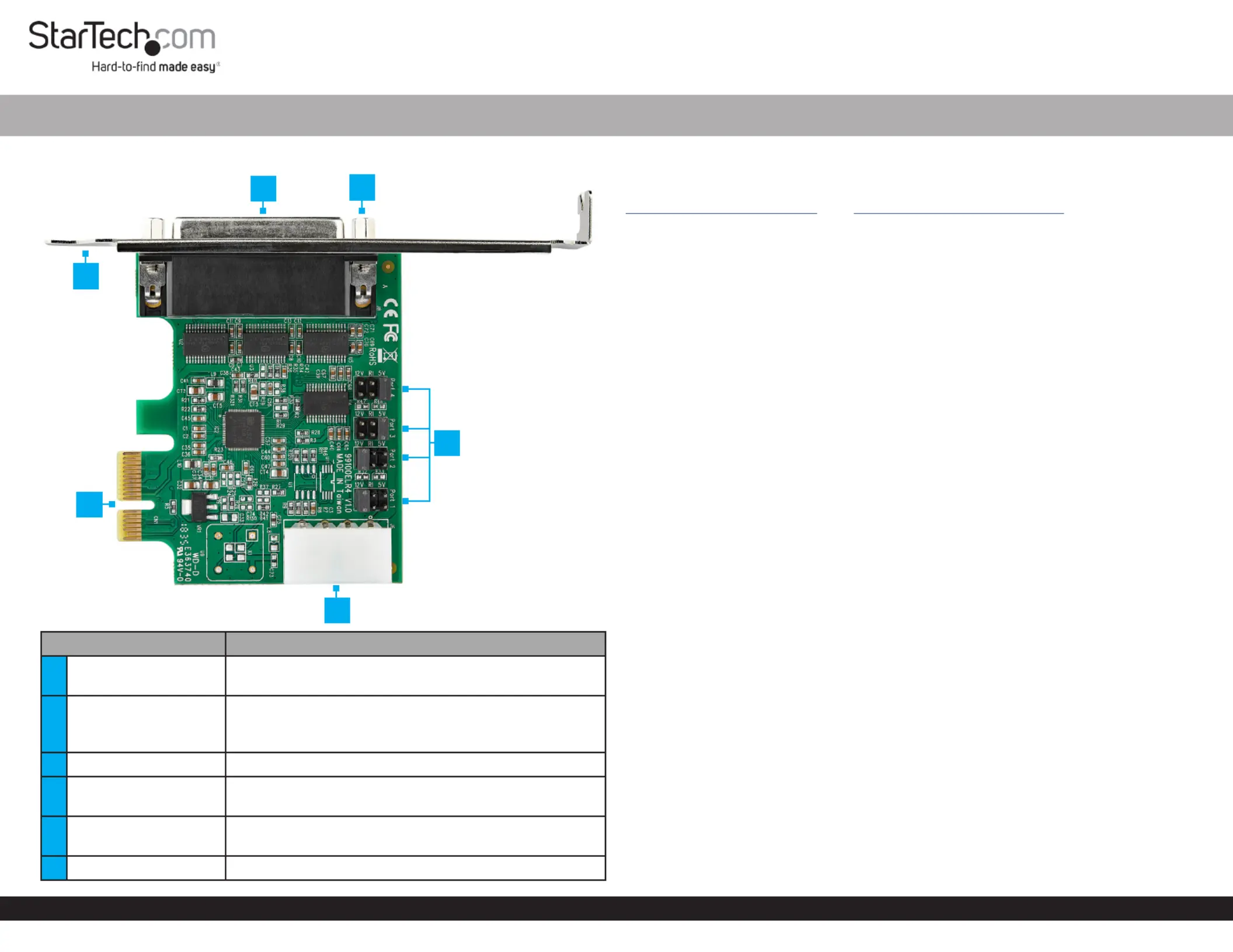
Product Diagram (PEX4S953 and PEX4S953LP)
PortFunction
1Break-out Cable Port
• Connect the to connect 4-Port DB9 Break-out Cable
up to 4 Serial Devices
2Stand-os
• Attach the to the Bracket PCI Express Serial Card
• Secure the to the 4-Port DB9 Break-out Cable
Break-out Cable Port
3Bracket• Attach the to the PCI Express SerialCardComputer
4
PCI Express Bus
Connector
• Connect the to the PCI Express Serial Card
Computer Motherboard
5Jumpers
• Congure the individual power Serial Connector
settings
6LP4 Power Connector• Used to connect an LP4 Power Source
4-Port PCI Express RS232 Serial Card - 16950 UART
Requirements
For the latest requirements please visit:
www.startech.com/PEX4S953www.startech.com/PEX4S953LP. - or -
• PCIe Slot
• Needle-Nose Pliers
• (Optional) LP4 Power Source
Installation
WARNING!
PCI Express Serial Cards can be severely damaged by static electricity. Make sure
that you are properly grounded before you open the or touch the Computer Case
PCI Express Serial CardAnti-Static Strap . You should wear an when you install
any computer component. If an isn’t available, discharge any Anti-Static Strap
built-up static electricity by touching a large for several Grounded Metal Surface
seconds. Only handle the by its edges and don’t touch PCI Express Serial Card
the gold connectors.
Jumper Conguration
Note: This is specially designed to allow for power output PCI Express Serial Card
from the ninth pin of the for that support power Serial Connector(s)Serial Devices
over serial. conguration is a requirement when connecting Jumper Serial Devices
that require power through a .Serial Connector
The can be moved into one of three dierent positions in order to set the Jumper
power output voltage for the . The default setting for the Serial ConnectorJumpers
is , no power. The must be connected after conguring theRILP4 Power Connector
Jumper5V12V Jumper to or of power. To congure the , complete the following:
1. Ensure the isComputerPower O.
2. Locate the for andcarefully remove the . Lift the JumperPort One JumperJumper
straight up and o of the .PCI Express Serial Card
Notes: The is located on the right hand side, labeled as on the JumperPort 1
. Printed Circuit Board
Always hold the by the edges.Card
3. Determine the power setting that is required for .Port One
4. Position the over the set of that correspond with the desired JumperPinsSerial
Connector Power SettingJumper. See to determine where the Figure 1 should be
positioned.
1
4
6
3
5
2
Specyfikacje produktu
| Marka: | StarTech.com |
| Kategoria: | Niesklasyfikowane |
| Model: | PEX4S953LP |
Potrzebujesz pomocy?
Jeśli potrzebujesz pomocy z StarTech.com PEX4S953LP, zadaj pytanie poniżej, a inni użytkownicy Ci odpowiedzą
Instrukcje Niesklasyfikowane StarTech.com

9 Stycznia 2025
9 Stycznia 2025
9 Stycznia 2025
9 Stycznia 2025
9 Stycznia 2025
8 Stycznia 2025
8 Stycznia 2025
8 Stycznia 2025
8 Stycznia 2025
8 Stycznia 2025
Instrukcje Niesklasyfikowane
Najnowsze instrukcje dla Niesklasyfikowane
29 Stycznia 2025
29 Stycznia 2025
29 Stycznia 2025
29 Stycznia 2025
29 Stycznia 2025
29 Stycznia 2025
29 Stycznia 2025
29 Stycznia 2025
29 Stycznia 2025
29 Stycznia 2025