Instrukcja obsługi Optex FTN-AM
Optex Niesklasyfikowane FTN-AM
Przeczytaj poniżej 📖 instrukcję obsługi w języku polskim dla Optex FTN-AM (8 stron) w kategorii Niesklasyfikowane. Ta instrukcja była pomocna dla 15 osób i została oceniona przez 5 użytkowników na średnio 4.3 gwiazdek
Strona 1/8
< CONTENTS >
< FEATURES >
Multilingual instructions
Visit to the Web site to find
valious language versions.
https://navi.optex.net/manual/08697/
EN-1
EN
No.59-2263-2 2207-16
INSTALLATION INSTRUCTIONS
fit
fit
FTN-STStandard model with 2 PIRs
FTN-AMFTN-ST with anti-masking
Compact outdoor
detector
Compact outdoor
detector
series
series
WIRED MODEL
•Compact design
•190° adjustable bracket
•Intelligent AND logic
•Digital anti-masking (AM model)
•Wall tamper (option)
1 INTRODUCTION
1-1 BEFORE INSTALLATION......................................1
1-2 PARTS IDENTIFICATION......................................2
1-3 DETECTION AREA................................................2
2 INSTALLATION
2-1 INSTALLATION......................................................3
3 WALK TEST
3-1 WALK TEST...........................................................5
4 DIP SWITCH SETTING
4-1 LED........................................................................5
4-2 ALARM OUTPUT...................................................5
4-3 PIR SENSITIVITY..................................................5
4-4 ANTI-MASKING......................................................6
5 OTHERS
5-1 WALL TAMPER (OPTION) CONNECTION...........6
5-2 EXAMPLE OF EOL WIRING..................................7
5-3 LED LIGHT PATTERN...........................................7
6 SPECIFICATIONS
6-1 SPECIFICATIONS..................................................8
6-2 DIMENSIONS.........................................................8
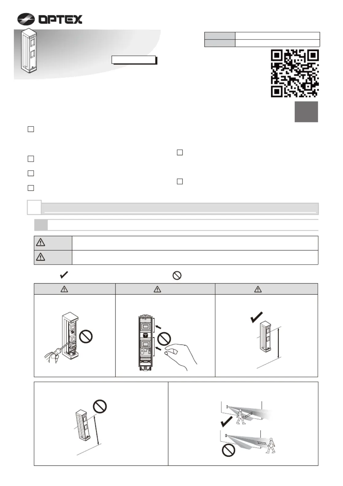
The check
mark indicates recommendation.
The nix
sign indicates prohibition.
Warning
Caution
Failure to follow the instructions provided with this indication and improper handling may cause
death or serious injury.
Failure to follow the instructions provided with this indication and improper handling may cause
injury and/or property damage.
Warning
CautionCaution
Do not remove the PCB.
ON
234
1
0.8 to 1.2 m
(2.6 to 3.9 ft.)
Parallel
Mounting height.
Tilt
Keep the detector parallel to the ground.
Consider the direction of the intruder,
for the setting of the detection area.
Do not touch the PCB except for the
DIP switch.
1
INTRODUCTION
1-1
BEFORE INSTALLATION
Specyfikacje produktu
| Marka: | Optex |
| Kategoria: | Niesklasyfikowane |
| Model: | FTN-AM |
Potrzebujesz pomocy?
Jeśli potrzebujesz pomocy z Optex FTN-AM, zadaj pytanie poniżej, a inni użytkownicy Ci odpowiedzą
Instrukcje Niesklasyfikowane Optex

21 Grudnia 2024
6 Grudnia 2024
6 Grudnia 2024
6 Grudnia 2024
6 Grudnia 2024
6 Grudnia 2024
9 Października 2024
7 Października 2024
5 Października 2024
5 Października 2024
Instrukcje Niesklasyfikowane
Najnowsze instrukcje dla Niesklasyfikowane
29 Stycznia 2025
29 Stycznia 2025
29 Stycznia 2025
29 Stycznia 2025
29 Stycznia 2025
29 Stycznia 2025
29 Stycznia 2025
29 Stycznia 2025
29 Stycznia 2025
29 Stycznia 2025