Instrukcja obsługi AMX HPX-600-NA
AMX Niesklasyfikowane HPX-600-NA
Przeczytaj poniżej 📖 instrukcję obsługi w języku polskim dla AMX HPX-600-NA (2 stron) w kategorii Niesklasyfikowane. Ta instrukcja była pomocna dla 43 osób i została oceniona przez 7 użytkowników na średnio 4.8 gwiazdek
Strona 1/2
QUICK START GUIDE
HPX--600/900/1200NA HydraPort 6, 9, 12 Module Connection Ports
Overview
The HPX-- --600/900/1200NAfamily of HydraPort Connection Ports (AMXFG560
xyz-NA) is built to accommodate the diverse connection needs of conference and
meeting room -- visitors. The HPX600/900/1200NAare designed to be mounted
into a horizontal surface such as a conference room table or lectern in order to
providudio/e connectivity for power, anetworking, video and control.
Specific connectivity is accomplished by populating the HydraPort Base
Assembly with various modules. Each base includes a single US/NAM power
outlet module already installed.
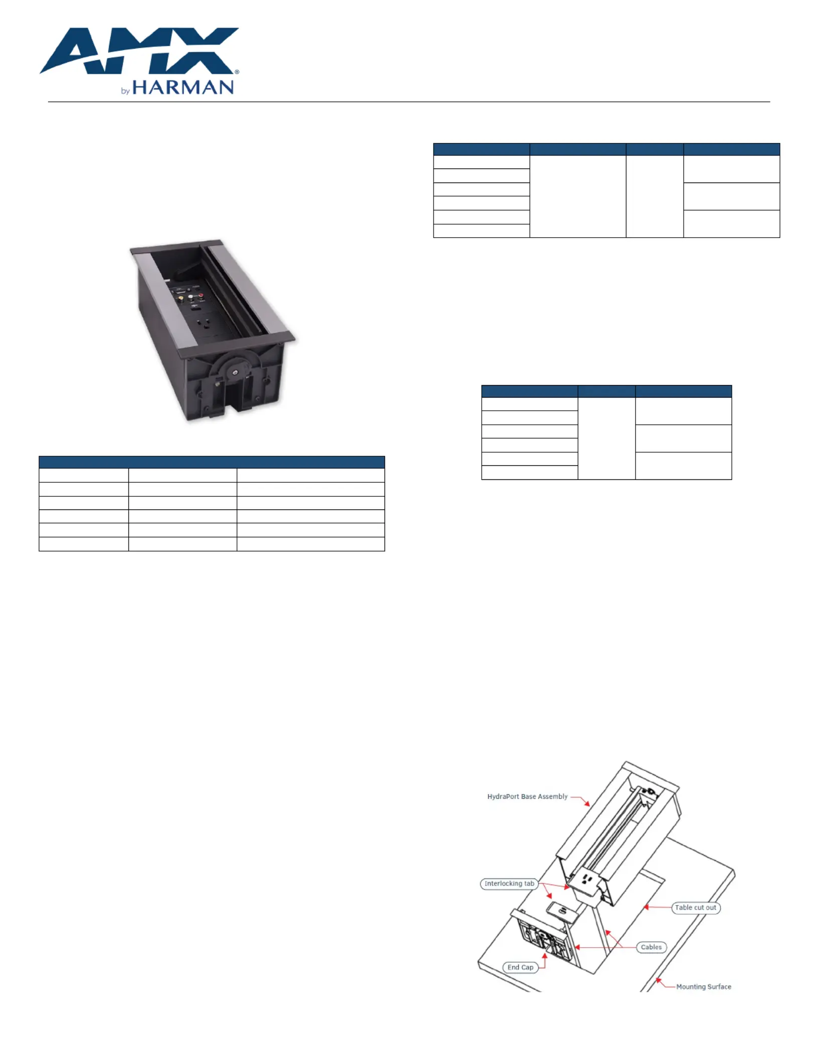
FIG. 1 AMX HydraPort Base Assembly
AMX offers six(6) versions o f the Hydraport Base Assembly for North America:
H--PX600/900/1200NA HYDRAPORT BASE ASSEMBLIES
HPX-- 600BLNA
AMX--FG56001B- NA
6M Capacity, Black
HPX-- 600SLNA
AMX--FG56001S- NA
6M Capacity, Silver
HPX-- 900BLNA
AMX--FG56002B- NA
9 M Capacity, Black
HPX-- 900SLNA
AMX--FG56002S- NA
9M Capacity, Silver
HPX-- 1200BLNA
AMX--FG56003B- NA
12M Capacity, Black
HPX-- 1200SLNA
AMX--FG56003S- NA
12M Capacity, Silver
ATTENTIONwith : Each base assembly comes one (1) US/NAM(Type A/B)
power outlet, -preinstalled. nly one (1) power outlet may be In North America, o
installed in any Hydraport Base Assembly.
ATTENTION: Only a professional, AMX-qualified installer should perform this
installation. Installation must conform to all local codes. This product may not
be installed by the end- user.
Accessories
Hydraport Base assemblies come with the following accessories:
•Two (2) Table adhesiveS”-/ pacers (for use in tables 0.50.75" thick) w
•Eight (8) Cable Routing Clips
Compatible HydraPort Modules
Please refer to the Architectural Connectivitys product pageat AMX.com for a
complete listing of compatible HydraPort Connection Modules
Installation of the HydraPort Base Assembly
The following sections describe the preparation, installation and setup of the
HydraPort Base Assembly. A typical installation will include several various
HydraPort modules.
Each HydraPort module has specific instructions for terminating their
connections. Refer to each miodule’s nstallation guide during the installation of
the HydraPort system.
Note: Read these instructions in their entirety before beginning the installation. The
installation requires specific steps to be performed in specific order.
CAUTION: This installation requires specific woodworking skills. This installation
should be performed by an experienced person, comfortable with these types of
woodworking operations. Improper installation may result in damage to the
mounting surface. AMX isnot responsible for damage caused by improper
installation.
1) Select a Suitable Location for the HydraPort Base Assembly
The following table indicates the space requirements for installing the unit:
M ODEL
H EIGHT
WIDTH
LENGTH
HPX-- 600BLNA
Base Height:
4.37”(111 mm)
Wi
th RCMs:
11.3”(287 mm)
5.43”
(138 mm)
8.19” (208 mm)
HPX-- 600SLNA
HPX-- 900BLNA
11.14” (283 mm)
HPX-- 900SLNA
HPX-- 1200BLNA
14.09” (358 mm)
HPX-- 1200SLNA
The HydraPort system requires a mounting surface from 0.5” (13mm) to 2”
(51mm) thick. T. hin surfaces may require use of included spacers
Note: Care should also be taken to ensure that the HydraPort system does not interfere with
the normal use of the work space. For example, on a table or work surface, ensure that the
system does not interfere with the user's legs when they are seated at the table.
2) iCut the Hole n the Mounting Surface
The Hydraport Base Assembly a paper template includes to locate the ideal
installation spot, and to mark the perimeter for cutting the surface. The following
table provides the hole cutout dimensions for the HydraPort Base Assembly:
M ODEL
WIDTH
LENGTH
HPX-- 600BLNA
4.84”
(123 mm)
7.64” (194 mm)
HPX-- 600SLNA
HPX-- 900BLNA
10.59” (269 mm)
HPX-- 900SLNA
HPX-- 1200BLNA
13.54” (344 mm)
HPX-- 1200SLNA
1.Use the template or measure the tabletop or other mounting surface to
locate the desired position of the HydraPort Base Assembly.
2.Use the cutout template to mark the edges of the cutout.
Note: Very little clearance exists between the HydraPort Base Assembly and the
hole cutout in the mounting surface.
Tips & Considerations:
•Align the cutout carefully with the edges or other features of the mounting surface.
If the cutout is misaligned, the installed unit will be misaligned.
•Take care to ensure that the top of the mounting surface is not damaged beyond the
width of the trim bezel as the cutout is made.
•Use an appropriate drill & bit to make a starting hole within the boundary of the
cutout. Use an appropriate saw, such as a jigsawto finish the cutout.
•Make sure cutting tool used is appropriate for the material to be cut and will not tear
or chip the top surface.
•Note that the process of making the cutout will create substantial dust and prepare
the environment appropriately.
3)Prepare the Terminations
Some HydraPort modules require some type of backside termination.
Note: Refer to the installation guide for each module to determine the required backside
termination.
FIG. 2 Inserting the Modules to HydraPort Base Assembly
Specyfikacje produktu
| Marka: | AMX |
| Kategoria: | Niesklasyfikowane |
| Model: | HPX-600-NA |
Potrzebujesz pomocy?
Jeśli potrzebujesz pomocy z AMX HPX-600-NA, zadaj pytanie poniżej, a inni użytkownicy Ci odpowiedzą
Instrukcje Niesklasyfikowane AMX

1 Stycznia 2025
1 Stycznia 2025
1 Stycznia 2025
1 Stycznia 2025
1 Stycznia 2025
7 Grudnia 2024
8 Października 2024
8 Października 2024
2 Października 2024
2 Października 2024
Instrukcje Niesklasyfikowane
Najnowsze instrukcje dla Niesklasyfikowane
29 Stycznia 2025
29 Stycznia 2025
29 Stycznia 2025
29 Stycznia 2025
29 Stycznia 2025
29 Stycznia 2025
29 Stycznia 2025
29 Stycznia 2025
29 Stycznia 2025
29 Stycznia 2025